Continue to Site

Welcome to EDAboard.com

Welcome to our site! EDAboard.com is an international Electronics Discussion Forum focused on EDA software, circuits, schematics, books, theory, papers, asic, pld, 8051, DSP, Network, RF, Analog Design, PCB, Service Manuals... and a whole lot more! To participate you need to register. Registration is free. Click here to register now.

Simple and Cheap 12V to 15V converter

Status
Not open for further replies.

tmd_63

Member level 2
Member level 2
Joined
Nov 11, 2009
Messages
48
Helped
5
Reputation
10
Reaction score
4
Trophy points
1,288
Location
West England, Central China
Activity points
1,626
I need a simple and cheap PSU circuit to get around 15V from a 12V supply.
The circuit does not need any fancy smoothing etc, must use cheap capacitors etc. No expensive chips or inductors. It only needs to supply a maximum of 1A and nominal around 400mA.
But I must stress the circuit use the least amount of components and must cost less than $2
 
Last edited:

Dear tmd
Hi
It is simple ,
You have two way :
1- boost converter
2- RCT multiplier.
If you use boost converter , it will be simple and good , but not with 2$ .
So , i suggest you RCT multiplier.
Regards
Goldsmith
 

With output voltage > input voltage, you can choose between some type of charge pump circuit, or a boost converter. At up to 1A I don't think a charge pump circuit would be practical (and 12 -> 15V inconvenient values), so you're looking at a boost converter like others already said.

Maybe I have a gap in my knowledge, but I don't see how you can do that without an inductor. Step-down yes, step-up not. Also I doubt you can get the whole for under $2 :roll: (LM25xx + inductor + capacitors + ...)
 

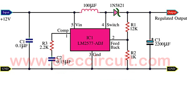
Like Klystron says you can use LM2577


or also high efficient and cheap MC34063, here is calculator :

**broken link removed**


Design 12V to 15V 1A 0,1V ripple, minimal input voltage 10,08V:
MC34063 12V to 15V Circuit.png


MC34063 price is about 0,4eur piece.
 
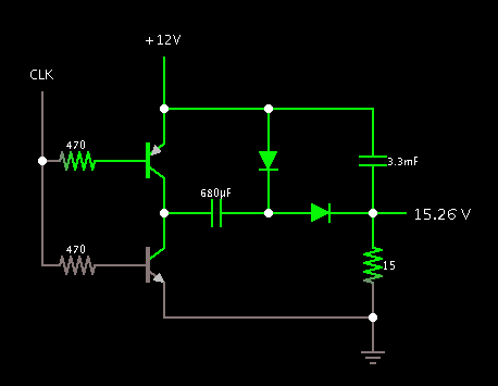
The schematic below will add a few volts to a positive supply.

It is typically a charge-pump doubler, or would be if the first capacitor were larger. However by adjusting the first capacitor downward, it carries less net current.

The smoothing capacitor reduces ripple. Its value can be adjusted as desired.

Except for the bias resistors, components must be able to carry up to 3 A peak.

The 15 ohm resistor is the load.

80_1345285088.png
 

I need a simple and cheap PSU circuit to get around 15V from a 12V supply.
The circuit does not need any fancy smoothing etc, must use cheap capacitors etc. No expensive chips or inductors. It only needs to supply a maximum of 1A and nominal around 400mA.
But I must stress the circuit use the least amount of components and must cost less than $2

I think just PCB will be over 2USD.
 

I think just PCB will be over 2USD.
Hi My friend dear tpetar
What you said ? it's PCB price higher than 2USD ?? are you sure ? in my city it's price will be around 0.08USD ( because it is too compact ) :grin:
Best Regards
Goldsmith
 

Hi Goldsmith, how are You?

I think that this is hard possible to achieve with budget up to 2USD, at my place for sure. Semiconductors parts sellers shaking prices in catalogs often. Even for Ćuk converter this is to low price. Just coil at my place is around 1EUR. :wink:
 

Hi tpetar
I'm fine thank you , how are you today ?
but it is possible ! price for a one layer board per each Cm^2 is around 0.25 USD . and when i make boards in my home the price will be pretty lower than this !! ( most of the times i make my boards in home )
Just coil at my place is around 1EUR
Wow what a high price is that for a coil ! what is type of it's core ? some days ago i bought a coil ( most of the times i prefer to wind my own coils in my home ) with inductance around 1mH for one A , current ,
It's price was around 0.35USD . i still have it .
:grin: Best Regards
Goldsmith
 

You can use UC3845 and a PNP transistor (driven by NPN transistor) with an inductor to design a boost converter. The UC3845 can provide output regulation by using non-isolated feedback employing a resistive voltage divider circuit. I don't know how much parts cost in your country. But over here, the whole circuit would cost around $1 - $1.5, including PCB.
 

The schematic below will add a few volts to a positive supply.

It is typically a charge-pump doubler, or would be if the first capacitor were larger. However by adjusting the first capacitor downward, it carries less net current.

The smoothing capacitor reduces ripple. Its value can be adjusted as desired.

Except for the bias resistors, components must be able to carry up to 3 A peak.

The 15 ohm resistor is the load.

80_1345285088.png

hi! what i am supposed to connect to the CLK? and what diodes i should use(talking about those 2 diodes in the picture)?
do you think this could handle the currency if used for car amplifier? or will the circuit fry?

would this circuit work for increasing the voltage from 12v to 15v for car amplifier? --> https://www.amazon.com/NightFire-Fixed-Voltage-Regulator-Supply/dp/B005PREKOU
 
Last edited:

would this circuit work for increasing the voltage from 12v to 15v for car amplifier? --> https://www.amazon.com/NightFire-Fixed-Voltage-Regulator-Supply/dp/B005PREKOU

The description says it is a regulated supply designed to use the 7800 series of 3-pin IC regulators. To use this type, you must apply a higher voltage than your desired output V. At least 2 V higher.

It will not turn 12V into 15V.

hi! what i am supposed to connect to the CLK? and what diodes i should use(talking about those 2 diodes in the picture)?

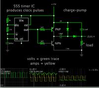
The popular 555 timer IC is suitable to provide clock pulses.

Here is a complete schematic.


It was made in the animated simulator at www.falstad.com/circuit.

If you click the link below, it will open the website, load my schematic, and run it on your computer. (Click Allow to load the Java applet.)

https://tinyurl.com/9n693hz

You can adjust values to see what affects what. Right-click on a component to bring up an edit window.

do you think this could handle the currency if used for car amplifier? or will the circuit fry?

It is unregulated. Output voltage will rise with a light load. If you need to protect your equipment from overvoltage, then you must regulate the output. The unit from Amazon would be suitable for this purpose as long as you need less than 1A.

It is adequate to provide your initial spec of 400 mA nominal. Notice the screenshot shows a load of 600mA. The output voltage drops according to how much current your load draws. The louder you run the amp, the more current it draws.

The 3300 uF capacitor can provide brief 1A output. You can extend this a little by using a higher farad value (a typical practice).

You must select components to be able to carry up to 2 A peak current.

The bias resistors have to be adjusted to make the transistors conduct sufficiently.

The transistors should be medium power general purpose. They do not need to be a matched (complementary) pair. They may need heat sinking.

The diodes can be ordinary 50V 3A type. They do not need to be fast recovery or low barrier type.

This is an inexpensive method to do what you want. It is not guaranteed to be easier to make and adjust than the methods suggested above.
 
Status
Not open for further replies.

Part and Inventory Search

Welcome to EDABoard.com

Sponsor

Back
Top