Hi,
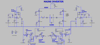
We are doing a simple "mains inverter" at approximately 300W. (will extend it to 3kW later)
Do you see any issues with this?
LTspice and .PNG schem attached.
As can be seen, the voltage output is not sinusoidal,
and no attempt is made toward that, because the only loads it may ever power will be
SMPS's of <75W which have a diode bridge/smoothing cap front end, or a Boost PFC
at the front end, and a sinusoidal waveform simply is not necessary in these cases.
Often the load will be 2kW Bass guitar amplifiers which have Boost PFC front end.
Also , Sometimes, the load will be a household kettle, and sometimes the load will
be a cheap fan heater. Most of the time the loads will be boost PFC'd battery chargers.
So if the prime power is a battery, then it gets boosted up to 400V, and then the
"inverter" does the rest.
Also, many cheap petrol generators cannot drive loads which are not resistive or well
power factor corrected, and so for those, we will feed them into a Boost PFC which gives the
required 400V output for the shown inverter to feed off.
We will improve the phase margin first, but the attached seems workable anyway.
We would simply have a 400VDC output , but cant do that as it makes fusing awkward and any
sudden breaks of the circuit can cause too much sparking, (not to mention the safety hazard of high voltage DC)
so we relented and
went for the shown AC output. We have another version of this which has a lower frequency of 5Hz.
As such, it has lower standby power because as you know, a mains inverter has to charge up and
discharge its output capacitor from -325V to +325v every 10ms, and so with the lower
frequency, we will reduce the standby power.
So any thoughts?


