Vermes
Advanced Member level 4

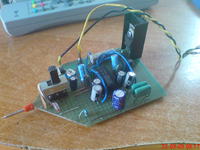
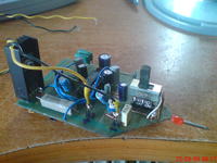
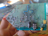
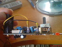
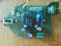
It is a simple tool, very useful in a lab, inspired by kit jabel j-47. It allows the location of faults in the low and high frequency tracks. The PCB was cut in the shape of the probe, and a pin of multimeter measurement proble was soldered to the input. Input circuits consist of the switch of the kind of tested system. Signal goes directly from the input through a switch and potentiometer for tested circuit of low frequency to the power amplifier of the finder. When you test high frequency track, it goes through detection circuits consisting of two germanium diodes and ceramic capacitors, then through a switch and potentiometer to the power amplifier. Power amplifier was realized on the system TA7769P. Headphones or speakers can be connected to the outputs of power amplifier. Assembly potentiometer allows you to set the volume in headphones or speakers. The system is powered from a 6V stabilizer (L78S05+2x1N4148). The whole can be powered by 8-35VDC.
Pictures:

Link to original thread - Szperacz/szukacz sygnału