Continue to Site

Welcome to EDAboard.com

Welcome to our site! EDAboard.com is an international Electronics Discussion Forum focused on EDA software, circuits, schematics, books, theory, papers, asic, pld, 8051, DSP, Network, RF, Analog Design, PCB, Service Manuals... and a whole lot more! To participate you need to register. Registration is free. Click here to register now.

Short version of help for the ICD2

Status
Not open for further replies.

ScratchBuild

Member level 2
Member level 2
Joined
Nov 8, 2006
Messages
51
Helped
2
Reputation
4
Reaction score
0
Trophy points
1,286
Location
South Africa
Activity points
1,705
potyo icd2

Hi guys and newbies,

I started this thread because I cannot see any of you guys trying to build the ICD2 reading 55 pages and then try to figure out what and where to go with this.

I will post what I have but does not guarantee it is the latest. So if you have later stuff than me please feel free to post.

Regards

Nic

Added after 11 minutes:

Here is the latest firmwares I use:

There are tjree firmwares for the 4550
1) The first one is the original
2) The second is the fix for the firmware overwrite problem
3) the third disables MCLR

Regards

Nic
 

potyo icd2 firmware overwrite problem

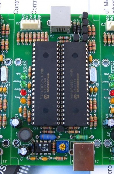
Here is the files for the schematic and PCB that I downloaded from Potyo's site quite a while ago, but I have built it as is and it works correctly. The only problem I have with it is that when I made the PCB the tracks are very thin and the via's does not have very much space to solder on:


The pcb and schematic is in eagle format. You can download a free version here:


Regards

Nic

Added after 1 minutes:

The link to the Microchip ICD2 site is:

**broken link removed**

Regards

Nic

Added after 2 minutes:

Some very good advice I used to do fault finding:

JQL said:
Hello Gonza

Erasing Target Device...
...Erase Succeeded

It reported only that, MPLAB ICD2 executed "Erase" operation, but didn't execute "verifying" operation.

Blank Checking...
...Program Memory
...Device not blank

It reported a true state, Program Memory is not blank.
That is, due to the VPP voltage too low, "Erase" operation no succeeded actually.

I suggest that, to give the VPP voltage your attention.
Move MCP41010 out of it's socket.
Then do following examinations by multimeter for MC34063.

Do not anything. R10(2.2k) is disconnected and is not reacting.
Here MC34063's output voltage VPP rest with R4(10k) and R9(1.5k), and is minimum.

VPP_min = 1.25v * (1 + R4/R9) = 1.25 * (1 + 10k/1.5k) = 9.58v

Short circuit DPOT1 and DPOT2, make sure That R10(2.2k) is parallel connected to R9(1.5k).
Here MC34063's output voltage VPP rest with R4, R9 and R10, and is maximum.

VPP_max = 1.25v * (1 + R4/(R9*R10/(R9+R10)) = 1.25 * (1 + 10k/(1.5k*2.2k/(1.5k+2.2k))) = 15.26v

Base on above examinations, validate that, if MC34063 can work normally.

Victory is at hand.
胜利就在眼前。
JQL
2007.08.13

Regards

Nic

Added after 8 minutes:

Some more good advice, not nescessarily in the right order:

JQL said:
Hello Gonza

I'm always giving your clone my attention.

"First of all check the voltage using multimeter on 18F877's RA3 pin (5th), and on the VPP-GEN rail.", potyo's word, is important.

First is to affirm the state of detection system. Here inconsiderate of that for the moment, if VPP_GEN's and VPP's values are correct.
If VPP_GEN's value by multimeter is approximately equal to VPP's value by MPLAB ICD2, then show that for us, the scale relation of 2.2k and 6.8k is normal, and MPLAB ICD2's detection is right.
Or else, check these resistors.

VPP_GEN / V_RA3 = (6.8k + 2.2k) / 2.2k = 9 / 2.2
(R5=6.8k, R11=2.2k in your P*otel SCH)

if VPP_GEN = 13.0v, then V_RA3 = 3.18v
if V_RA3 = 2.4v, then VPP_GEN = 9.82v

Second is to correct VPP_GEN's value.
Check 10k, 1.5k, 2.2k resistors and other doubted place.
(R4=10k, R9=1.5k,R10=2.2k in your P*otel SCH)

I wish you success.

JQL
2007.08.12

Regards

Nic

Added after 5 minutes:

Some clever help from Mr. potyo himself:

potyo said:
USB LED lights or blink, when there is a problem with the usb connection.

Almost every chip needs different OS, this is the reason, why MPLAB sends new OS, when you select another chip.

Powering from ICD2 is fully independent from programming and debugging. If your target board has its own power supply, or it is running for example at 3.3V, then you should deselect that checkbox. Powering from ICD2 is useful only for experimenting or programming chips, which are not in target board (like old programmers with ZIF socket and similar).

**broken link removed**

There are some minor changes on the board.
1. There is no need for 4066, which can be powered from 13V. Now you can use any 74HC4066. I've added one resistor (R42) and one zener diode (D2) to make this feasible
2. I've added one pull-up resistor (R43) to 16F877's RA4 pin, because sometimes happened, that unchecking the checkbox to power target from icd2 has not disabled it physically.
3. I've removed diode and jumper from 4550's Reset pin, there is no need for it.

You can download the schematic and PCB from here: **broken link removed**

As you see, if you have built my earlier clone, you can need (if you want) to add only that pull-up resistor. you can simply add an SMD or an classic resistor to the bottom side, like on this picture: **broken link removed**

Added after 4 minutes:

Here is a search to find all Potyo's reply's in the actual forum:


Added after 2 minutes:

One thing everybody always forget is the jumper that must be installed on the two pins near the 74HC4066.

Added after 2 minutes:

Remember the main thread for building the icd2 is:


Added after 10 minutes:

One piece of advice that was very good for me from potyo:

potyo said:
Hi
Idea for peoples with an unworkable icd2.
Remove the 4550 and short connect its pin 36 with vcc. Now check the voltage on 877(A)'s MCLR pin. It should be <0.5V. If it is't then replace the transistor with another type(if you have used BC337, replace with BC546 for example).
I had similar problems, as you, and checked the voltage on that pin, and received, that it was near 2.5V(in this case 4550 can't reset the 877, and can't download the firmware).
Another idea: program the 4550 with an old version of it's firmware(i have used zedman's firmware from the beginning). Connect to pc, and ask MPLAB(i've used version 7.41) to connect to it. It you hear the usb disconnect/connect sound 2-3 times, and MPLAB wants to update the firmware, then you know, that the connection to pc and the driver is ok, and the problem is between the chips.
 
Last edited by a moderator:

icd2 potyo

Have you found a schematic close to Microchip's design without many function loss?
 

code asm master_slave i2c

AS far as I know there is not any function loss. It uses the same operating system that Microchip does.

Regards

Nic
 

potyo new version resistor

Mine Notes:

1) Only after Windows is on plug in usb on ICD2
2) Only after Windows if off unplug ICD2 from usb
3) Only when is deselected ICD2 in menu in MPLAB disconnect ICD2 from target pic
If something from pints 1,2,3 happened just clean USB driver and reinstall again.
 

ds1820 to max7219

Here is a link to a USB monitor program to assist in debugging:

https://www.hhdsoftware.com/Download/usbmon.exe

Regards

Nic

Added after 9 minutes:

Hi there,

Here is an explanation of the leds on potyo's ICD2:

potyo said:
I have finished the schematic. Please check for errors. Probably have placed too many LED's, their function is:
LED1 - USB Connected
LED2 - Error
LED3 - Busy
LED4 - VDD is present on the target device
LED5 - VPP is present on the target's MCLR
LED6 - VPP source is working
LED7 - Power LED
J3 is to select ICD's power source (USB bus/target device). I don't know, why original ICD2 uses 74HC125 and 126, i have copyed this from the original's schematic. Anyone knows what is on the pin 6 of the original ICD2?
I hope, the board will be finished on the next weekend, but it's not sure(if i have test, that has higher priority). The schematic was drawn in Eagle, if you want, i can also upload the source files.

Added after 1 minutes:

Oh yes, and if you finished your ICD2, please go and thank everybody on the main thread for building this project. They have spent hours and hours to make this possible:D
 

lothar stolz

where is the schematic of ICD2? I still don't get it.
 

how to connect icd2 in mplab 7.60

Hi there,

Just follow the link I gave above:


Regards

Nic

Added after 1 minutes:

Remember the schematic and PCB is in eagle format.
 

icd2 com speed baud

Hi,

I want to know some features of the two version...
E.g. :
Do the two versions of the ICD2 clone (the PICS and the Potyo2) need to connect a power supply ?

When I look the Potyo's version, I can see three conector ? Does it mean that it is the power jack connector ??

About the auto-selection of the Vpp (for an use with all the PIC), which of the both provide this function ?

Briefly, what are the features of each version ??

Many thanks !
 

inchworm icd2 rj11

ハン said:
Hi,

I want to know some features of the two version...
E.g. :
Do the two versions of the ICD2 clone (the PICS and the Potyo2) need to connect a power supply ?

When I look the Potyo's version, I can see three conector ? Does it mean that it is the power jack connector ??

About the auto-selection of the Vpp (for an use with all the PIC), which of the both provide this function ?

Briefly, what are the features of each version ??

Many thanks !

First of all I did not build the PICS version, so I cannot quote on its abilities.

With potyo's version the three pins is not for connection power but for a jumper switch. With Potyo's verion you can power the Target board from the USB bus but it only allows for about 100mA to be drawn from it (a USB bus restriction). So you can program individual chips from it but not the whole target board. Otherwise you have to supply your own Vdd to the target board.

I have not tested my ICD2 with 3.3V chips. So I cannot comment, I know there is a thread that specifivally discusses this. I am also almost sure that Potyo's version is not doing it automatically, but anybody can correct me if I am wrong.

Regards

Nic
 

74hc4066 eagle

Hi ScratchBuild...
In my preview post I said :
"When I look the Potyo's version, I can see three conector"
But I wanted to say "In the PICS's version"...

Well, in the PICS's design there is really three connectors...
Two at the top, and one at the bottom...

2_1199802725.jpg


You can see it in the picture at www.icd2clone.com
 

pic18f 3.3v icd2 icdwarn0020

Does any one has a good experience with problem ICD2 and dSPIC and desire to open same tread as this one? From me one more time great work to all in tread “clone ICD2” especially to PICS. His ICD2 is easy to build and works stable.
 

potyo icd2

there is no problems with ICD2 and dsPICs, just as with PIC24... but the PICS you've built will not work with 3.3V devices. only potyo2 supports them.

0x41 0x56 0x45!!
 

mplab icd2 debugger unavailable

Thanks, this is a information. For PICS ICD2 I prepare to make a interface 5V<->3v3 with MAX3378. As soon I make it I will sent it on the tread. Lets make and share good things!

Added after 4 minutes:

With scheme now.
 

idc2 clone

Hi,
Does anyone find the true PICS's ICD REV C ???
In the icd2clone site there are only the rev B, for the both link !!!

I want to know what is the third connector of the REV C image, it's not present on the REV B schematic...

I also want to know the PICS version features vs Potyo's version...
Which is the better ??

Thanks !
 

icd2+pin out rj11

Original comment from PICS for C version:

Post20 Dec 2006 9:42 Re: Project to replace CY7C64613 in the ICD2 Reply with quote
Report this post to the moderators of this forum
Rev.C is double sided board with minor modification :
added pot for adjust Vpp(9v..14v)
added resistor for mclr PIC18F4550
and change capacitor for oscillator with 12pF(C6,C7)

Third connector seems to be parallel to RJ11 as option to use RJ11 or that one (5 pins in line). I use that one on all target boards.
 

max3378 eagle

DraganM,
Do you have the REV C files (schematic, pcb, hex, etc...) ?
I can't find them nowhere !
PS: What is the reason of an adjusting Vpp from 9V to 14V by the pot ? With it, does the REV C able to program the PIC24 which functions at 3,3V ??

Thanks !
 

edaboard adjusting vpp

I use rev. B and just replace resistor R1=20K with multiturn pot. 22K and do the job. Adjust on 12,5V and that is. Do not worry rev. B is really same as C but the differences describe by PICS which I sent last time in this tread. Just make ICD2 rev. B plus describe the differences and start use it, that is fun.
 

icd2 vpp adjust

the answer to your question has ben stated milion times so far. and it takes just a few seconds looking at the schematics, to see that PICS does not support 3.3V devices, because it has no hardware to do the level conversion. that is the basic, and probably the ONLY difference between PICS and potyo2.

potyo2 CAN program and debug BOTH 3.3V and 5V devices (PIC24, dsPIC) (basically it can debug and program any target which is powered with VCC from 2 up to 5V)
PICS CANNOT program or debug 3.3V devices (basically it can program and debug ONLY targets which are powered with VCC=5V)

this ONE & ONLY difference affects ONLY the complexity of the design. PICS has just 3 ICs, whereas potyo2 has 8.

potyo2 is more accurate copy of ICD2, while PICS is a simplified version which cannot operate with low voltage devices.

how many times this has to be said?

0x41 0x56 0x45!!
 

idc2 busy always led on

I have a couple of questions that I could not find answers to in the original post:

I built the Potyo2 version. It connects, loads the driver, loads the OS, and passes the self-test. I cannot get it to read/write/verify/debug ANY chips.

1) When programming a chip, do you need to supply a clock signal (crystal), or does that come from the ICD2?

2) I used a 7407 since I cannot find a 74LS07 locally. Is there any difference between them other than power consumption?

Thanks
 

Status
Not open for further replies.

Part and Inventory Search

Welcome to EDABoard.com

Sponsor

Back
Top