Continue to Site

Welcome to EDAboard.com

Welcome to our site! EDAboard.com is an international Electronics Discussion Forum focused on EDA software, circuits, schematics, books, theory, papers, asic, pld, 8051, DSP, Network, RF, Analog Design, PCB, Service Manuals... and a whole lot more! To participate you need to register. Registration is free. Click here to register now.

[SOLVED] Serial to USB virtual com port using PIC16F73

Status
Not open for further replies.

Mithun_K_Das

Advanced Member level 3
Joined
Apr 24, 2010
Messages
899
Helped
24
Reputation
48
Reaction score
27
Trophy points
1,318
Location
Dhaka, Bangladesh, Bangladesh
Visit site
Activity points
8,254
Is it possible to make a virtual COM port using PIC16F73 via USB cable ? If there is any way to make a communication using just USB cable it will be great.

Note: I know USB communication, Serial Communication well so don't ask any odd questions.

What My plan is to know if it is possible to make a communication between PIC16F73 and PC via Serial communication without using any MAX232 and Serial cable.

I just want to use USB cable. No MAX232 or serial to usb converter. Is it really possible with PIC?

I found many examples but they are all with ATMEGA8. So my curiosity is, if its possible with PIC16F73 as both atmega8 and PIC16F73 have no USB module inside. So if its possible with atmega8, then it should be possible with PIC16F73.

TIA
 

You need to implement a USB communication device (CDC) on top of the 16FUSB core. CDC can be connected under Windows as virtual com port.

Apparently there are no readymade code examples.

Considering that there are many serial communication code examples for USB enabled PIC microcontrollers, the whole project sounds a bit like reinventing the square wheel.
 
Thanks FvM. So, all I need to do to make a virtual COM port with these 16FUSB core? Ok, then can I put data in these PIC16F628A (as found at google) using 2 pins as Tx, Rx line UART PINs?
 

I'm not sure I understand the question. Are you asking for the 16F73 to work as a direct USB interface, with D+ and D- signals connected directly to the PIC?

You cannot emulate USB in firmware unless you have a significantly faster processor and for full compatibility, a faster UART port as well. You still need voltage level shifting if you want to match RS232 compatibility. It sounds like what you are asking for is a clone of one of the many FTDI/Prolific Technology USB-serial interfaces so why not use one of those instead. If you want USB on board the PIC, use one of the device with a built in peripheral such as the 18F2550/4550.

Brian.
 

all I need to do to make a virtual COM port with these 16FUSB core
That's the basic idea, but I have seriously no idea if it will be an easy or rather hard job. I only traced the software USB concepts out of general interest but wasn't yet tempted to implement it.

Many years ago, I started an USBN9603 CDC project from the scratch, and I remember well that simple things like defining the right descriptors to be understood by the Windows driver can be tedious way of trial and error.

So you should copy as much existing code as possible (e.g. from the Microchip Application Library). You still need a profound understanding of USB operation and the design of the respective software libraries.

- - - Updated - - -

You cannot emulate USB in firmware unless you have a significantly faster processor and for full compatibility, a faster UART port as well.
You can, if you restrict the interface to slow 1.5MBit/s USB, that's what the said 16FUSB and respective ATmega software libraries do. If you think it's a weird idea, I won't disagree...

I didn't check specifically if 16F73 is fast enough, but other 16F processors can do.
 
Frankly, other than simply the challenge to accomplish the task, I see no real motive for attempting it.

The PIC16F73 has a maximum system clock (Fosc) frequency of 20MHz, however as the instruction clock (Fcy) frequency is a Fosc/4 for the PIC16F series, an Fcy of 5MHz certainly presents a major limitation. Then one must consider the RAM requirements for a soft USB implementation, the limited remaining RAM another limitation for implementation of another task. Of course, then there is the matter of the Low Speed USB throughput, probably sluggish at best, with questionable USB 1.1 compliancy.

As already mentioned, Microchip offers several low cost microcontroller with Full Speed USB 2.0 compliant (12 Mb/s) hardware interfaces, for example the PIC16(L)F1454/5/9 series. Several can be purchased for less than $1 USD, in quantity, a third the cost of the PIC16F73 and considerable more capable, with an Internal OSC, Fosc of 48MHz, EUSART, SPI, etc.


BigDog
 

Thanks Brian, Yes I was planning to use PIC16F73 instead of FTDI because FTDIs are not available at our local market. But PIC16F is available. So I was looking for if there is any way to use PIC16F73 instead of FTDIs.
 

Seems like it is not possible with PIC16F73. But I'm confused how can a atmega8 works even with a 16MHz Crystal. I'm don't work with AVR MCU. So have no such deep idea to implement that.

- - - Updated - - -

India and Bangladesh are not a same country. And here to get a 1$ device will cost another 35$ in total cost including TAX and bribe to get the product in hand. There is no easy way to get lower quantity.

Last year I bought a software of 259$ and it costs 315$ in total excluding that 259$ of software price to get that in my hand. :(:sad:


@ BigDog.
 
Last edited:

Unlike the PIC16F series, the ATMega series have a Fcy equal to the Fosc, in other words if the system clock is operating at 16MHz, an ATMega can typically execute an instruction in a single system clock cycle versus an instruction executed every four system clock cycles for the PIC16F. Which puts PIC16F series microcontrollers at a disadvantage from the start. There are of course several other hurdles to consider.

While it is certainly possible, other than the shear challenge to accomplish the task, it makes very little sense to attempt it.

Rather, a more prudent expenditure of your time and energy would be finding alternate sources for more appropriate microcontrollers fitted for the task.

If components are as difficult to come by in your area, perhaps you should consider buy quantity and reselling.


BigDog

- - - Updated - - -

India and Bangladesh are not a same country.

I realize they are not the same country, my mistake.
 

AVR has single clock cycle instructions, so it's faster. But 16F628 used in the original 16FUSB project is a 20 MHz processor as well, so it's apparently possible somehow. It's pure assembler code, I guess you won't have fun to add CDC or just port it to a different PIC16 processor.

- - - Updated - - -

I see that there are shops like Techshop in your hometown, offering PIC18F2550 and also FT232. www.techshopbd.com
 

I fear, alternatives are: pay 4 - 5 USD for a FT232 from your local supplier or spend some months developping the code, with no guarantee that it works at the end.
 

AVR has single clock cycle instructions, so it's faster. But 16F628 used in the original 16FUSB project is a 20 MHz processor as well, so it's apparently possible somehow. It's pure assembler code, I guess you won't have fun to add CDC or just port it to a different PIC16 processor.

After a bit more research, apparently one of the techniques the 16FUSB implementation employs to surpass the Fcy limitations of the PIC16F series, is overclocking the PIC16F628A Fosc to 24MHz from its normal 20MHz maximum Fosc.

The development of such a firmware really isn't a trivial thing, especially taking into account the limitations of a
simple microcontroller, such as the PIC16F628/628A, especially with regard to its speed.

A PIC16F628/628A can work with frequencies up to 20MHz. However, each instruction cycle takes four clock cycles.
This means that, in fact, with a 20MHz crystal we have our PIC running on 5MHz (20 / 4 = 5). Doing a little overclock,
with a 24MHz crystal, we can run programs on 6MHz (or 6Mips).
Since the speed of the USB low-speed is 1.5 Mbps,
we can obtain a total of four instructions (6 / 4 = 1.5) to treat each bit of data during transfer. That is, each bit of the
USB bus takes the time of four instructions of our PIC.

As it's not hard to see, with only four instructions to encode/decode the NRZI, insert/remove the bit stuffing and even
check the end of packet (EOP), the work becomes impossible. Fortunately using a few more tricks we can work around
this problem, as we shall see.

The default endpoint, EP0, treats every control transfer messages. Although this transfer type is more used to the
device setup, we can use it for general purposes too. Additionally, it's possible to use IN and OUT interrupt transfer
enabling respectives endpoints on config file (def.inc). Interrupt endpoints are EP1 IN and EP1 OUT. If you're afraid
about using a device driver (libusb in our case), you may enable HID option, write your own Report Descriptor or use
the default one.


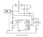
16FUSB.JPG


BigDog
 

Attachments

  • 16FUSB Project - 1.2.pdf
    723.6 KB · Views: 166

Status
Not open for further replies.

Similar threads

Part and Inventory Search

Welcome to EDABoard.com

Sponsor

Back
Top