Continue to Site

Welcome to EDAboard.com

Welcome to our site! EDAboard.com is an international Electronics Discussion Forum focused on EDA software, circuits, schematics, books, theory, papers, asic, pld, 8051, DSP, Network, RF, Analog Design, PCB, Service Manuals... and a whole lot more! To participate you need to register. Registration is free. Click here to register now.

serial communication of PIC 16F877A with pc serial port

Status
Not open for further replies.

kvns.kapil

Newbie level 4
Newbie level 4
Joined
Oct 12, 2010
Messages
5
Helped
0
Reputation
0
Reaction score
0
Trophy points
1,281
Activity points
1,461
Hi,
I am using pic 16F877A micro controller, Rs232 interface. I want to serial communication with computer to micro controller by transmitting and receiving data. I am writing code in MPLABIDE Please help me with some example programs or in any other way to improve my knowledge.
Thanks in advance.
 

Dear kapil,

First you study serial communication registers used in pic
This program will help u.
I think it's working one.

list p=pic16f877a
#include"p16f877a.inc"
cblock 0x20
r0,r1
endc
org00
goto main
org 04h
retfie
main bsf STATUS,5
movlw 0x24
movwf TXSTA
movlw D'48'
movwf SPBRG
bcf STATUS,5
movlw 0x90
movwf RCSTA
l1 btfss PIR1,5
goto $-1
bcf PIR1,5
movf RCREG,0
movwf TXREG
bsf STATUS,5
btfss TXSTA,1
goto $-1
bcf TXSTA,1
bcf STATUS,5
goto l1
end
 

Just start to writing program and if any difficulty then let us know.

first start with only sending data to pc and go ahead.
use uart to communicate and show your data on hyper terminal.


Piyush Manavar
 
I had started but, i am not recieving any data on hyperterminal
 

Just check your settings stopbits hardware and buad rates.
and then not working go to low baudrate


Piyush Manavar
 
Just check your settings stopbits hardware and buad rates.
and then not working go to low baudrate


Piyush Manavar

Hello,
Actually i had connected an led and switch to the controller, i wanted to display when switch is pressed and led to glow when we type on from keyboard, please suggest me how to write program for serial communication
 

to write this type of program go to this way

1-initialize all necessary hardware for key detection serial communication and enable serial interrupt
2-set baud rate and necessity settings (stopbits and frame of bytes)
3-continuously scan the key whether it pressed or not.
when pressed send data byte to PC
4-you have already enable interrupt so when ever you send byte to uc from PC program calls ISR for glowing LED.
to check that uc receiving or not data from PC you can write Eco back program in this nothing but what ever data you receive from PC just send it back to PC so that you can guaranty that you uc is receiving data.
 

The code for duplex serial communication is attached along with. Just copy it in the MPLAB IDE & check.
Also where are you planning to display the matter which you are typing? Is it just for you to simulate or to do in practical?
Regards,
Jerin.
 

Attachments

  • New Text Document.txt
    412 bytes · Views: 203

If you are having more doubts do check the data sheet(USART module of the controller) for the controller you are using & it is explained there.
Regards,
Jerin.
 

Hi,
Please i am doing a similar project only i am using PIC16f877A to connect to a bluetooth-enabled system over an RN 41 bluetooth module.i have three LM 35 sensors connected to the PIC and the PIC is meant to transmit the values it is receiving over the bluetooth to the PC.the problem is i have connected an LED to the TX pin of the PIC to indicate if it is ON but it doesn't seem to be transmitting because my LED is OFF.i have checked my connections.please i wont mind help.thanks.
this is the code i used in the PIC:

unsigned long int temp_res,vc;
unsigned int vdec, vrem;
unsigned char op[6];
unsigned char txt[7];

void Text_To_Usart(unsigned char *c)
{
int i;
i = 0;
while(c != 0)
{ // Send TEXT to serial port
Usart_Write(c);
i++;
}
}

void first_ana()
{

int i,j;
temp_res = Adc_Read(1); // Get results of AD conversion
PORTD = temp_res; // Send lower 8 bits to PORTD
PORTB = temp_res >> 2; //
temp_res=4888*temp_res;
vdec=temp_res/10000;
WordToStr(vdec,op);

j=0 ;
for(i=0;i<=5;i++)
{
if(op!=' ') // If a blank
{

txt[j]=op;
j++;
}
}
Text_To_Usart(txt);
usart_write(0x0a);
usart_write(0x0d);
}

void sec_input()
{
int i,j;
temp_res = Adc_Read(2); // Get results of AD conversion
PORTD = temp_res; // Send lower 8 bits to PORTD
PORTB = temp_res >> 2; // Send 2 most significant bits to RB7, RB6
temp_res=4888*temp_res;
vdec=temp_res/10000;
WordToStr(vdec,op);

j=0 ;
for(i=0;i<=5;i++)
{
if(op!=' ') // If a blank
{

txt[j]=op;
j++;
}
}
Text_To_Usart(txt);
usart_write(0x0a);
usart_write(0x0d);

}

void third_input()
{
int i,j;
temp_res = Adc_Read(3); // Get results of AD conversion
PORTD = temp_res; // Send lower 8 bits to PORTD
PORTB = temp_res >> 2; // Send 2 most significant bits to RB7, RB6
temp_res=4888*temp_res;
vdec=temp_res/10000;
WordToStr(vdec,op);

j=0 ;
for(i=0;i<=5;i++)
{
if(op!=' ') // If a blank
{

txt[j]=op;
j++;
}
}
Text_To_Usart(txt);
usart_write(0x0a);
usart_write(0x0d);

}

void main() {
ADCON1 = 0x80; // Configure analog inputs and Vref
TRISA = 0xFF; // PORTA is input
TRISB = 0x3F; // Pins RB7, RB6 are outputs
TRISD = 0; // PORTD is output
usart_init(9600);
do
{
first_ana();
delay_us(1000);
sec_input();
delay_us(1000);
third_input();
delay_us(1000);
}
while(1);
}


Can you post your circuit =)
 

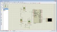
I don't have a concise circuit.but this link is just the idea of what i am trying to do.the virtual terminal sort of replaces the bluetooth module.i ran it on proteus and it worked fine.but i am having problems with getting the correct thing on the building.i'll appreciate any help.thanks


Two thing are there for you to check here. First is the configuration of PORTA is still analog or configured as digital. Second one is the baud rate setting of the terminal & the controller. If both the rates aren't the same then the controller won't show the desired output.
Regards,
Jerin.
 

Is this you first UART program? If so, why don't you make an easier program just to verify that you are really transmitting?
But, if this is not your first program, just check the answers above and verify.
 

Thanks for the tip guys....i'll note that.but please i just developed one small hitch.i noticed my c program on mikroC only compiles when i set the clock to 8MHZ.i have tried 4,16,20..it just won't compile.pls does anyone have an idea why that is happening?i appreciate the help.
 

can you pose your hitch.c here? =)
 

If you did not save the .c file after adding to the project this would happen i.e if you did add an old .c file to the newly created project with different frequency it shows error.
Regards,
Jerin.
 
RN41 to PIC

Hi, I am wondering if any of the members could help me explain how to connect the RN41 to PIC. Thanks
 

xxxxxxxxxxxx

i also provide u the source code vb2008..
 
Last edited by a moderator:

Status
Not open for further replies.

Similar threads

Part and Inventory Search

Welcome to EDABoard.com

Sponsor

Back
Top