Continue to Site

Sensor integration with microcontroller

LEROY180

Newbie level 5
Newbie level 5
Joined
Mar 5, 2025
Messages
10
Helped
0
Reputation
0
Reaction score
0
Trophy points
1
Activity points
134
I am designing a system to control a motor which will lift or lower a shaft. One mode is manual where it is controlled with a foot pedal, one for up and one for down. The automatic mode is hooked to a microcontroller, IBT-2, and ultrasonic underwater distance sensor. I am having issues with wiring and coding the sensor. More info on the sensor is in this link: Sensor Information

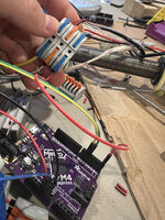
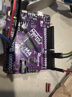
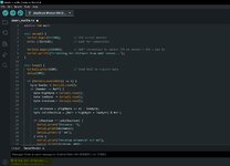
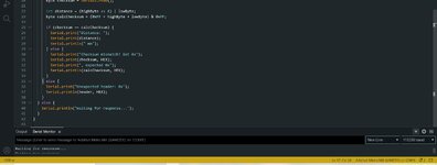
I can successfully wire up the IBT-2 motor driver and the microcontroller which is a Metro M4 Express. Using test code I can get the IBT-2, microcontroller, and motor to work. Then when I try to add in the sensor nothing will work. I am using Arduino IDE to write the code. Microcontroller is powered with 5v. IBT-2 will have 24v for power in and then motor wires out to the motor. VCC and REN and LEN on IBT are all wired to 5v on the microcontroller. RPWM and LPWM are wired to pins 5 and 6. Sensor is getting power, around 3v, it is also grounded and the yellow and white wires are where I think the issue is. I was trying to leave the white wire disconnected and just use the yellow wire to send data back to the controller. I wired the yellow wire to TX0 on the micro.

I am not sure what other wiring configurations to try or how to correctly code for the sensor. I think there may be an issue with the wiring and possibly not the coding.

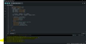
I have added an image of the wiring for the controller, IBT, and motor. The sensor information can be found in the link above. I can give additional details if I missed anything. Any information helps. Thank you.
 

Attachments

  • 1743277964087.png
    1743277964087.png
    2.8 MB · Views: 14
Hi,

let´s say you have two cell phones. One is defective the other is good. You bring the good one to the repair?

According your headline and description the sensor is the problem.
But your picture only shows the working circuit ...

So neither in the description nor in the picture we see how you connected your sensor.

***
Also we don´t see your test code.
We don´t know what you did for debugging the circuit. (Checking power supply, checking data transfer regarding timing and voltage levels...)

Klaus
 
Here are three images of the wiring I have been using for the sensor. I have tried leaving the white sensor wire disconnected because I am not sending anything back to the sensor, just getting data from the sensor.
Here is the wiring table for the sensor. In my images, the red is connected to 5v from a buck converter and the black wire is grounded. Yellow is connected in the terminal and wired to RX0 on the metro m4 express microcontroller.

Red lineVCCpower supply input positive pole
Black lineGNDpower ground wire
Yellow lineRXUART receiving data line
white lineTXUART transmitting data line

Not sure the best way for sending code, but I will put a couple pictures. I have tried several variations of code like this one and it always says something like waiting for response or it will say things like waiting for data from sensor, etc. I have posted a few images of code I tried.

I have used a multimeter on different locations throughout the wiring. I am getting 5v power into the sensor, the red sensor wire. I am then getting about 3.3v out of the yellow and white sensor wire.

Thank you for your response, if there is any information I can add that will clear things up, let me know. Thank you.
--- Updated ---

Hi,

let´s say you have two cell phones. One is defective the other is good. You bring the good one to the repair?

According your headline and description the sensor is the problem.
But your picture only shows the working circuit ...

So neither in the description nor in the picture we see how you connected your sensor.

***
Also we don´t see your test code.
We don´t know what you did for debugging the circuit. (Checking power supply, checking data transfer regarding timing and voltage levels...)

Klaus
My apologies Klaus, I think I replied to the entire forum thread when I meant to reply to your response, but the information I provided is in this and should clear up some things you talked about. Thank you
 

Attachments

  • unnamed (2).jpg
    unnamed (2).jpg
    1.1 MB · Views: 14
  • unnamed (1).jpg
    unnamed (1).jpg
    1 MB · Views: 9
  • unnamed.jpg
    unnamed.jpg
    848.6 KB · Views: 13
  • Capture.JPG
    Capture.JPG
    302 KB · Views: 14
  • Capture1.JPG
    Capture1.JPG
    263.6 KB · Views: 13
  • Capture2.JPG
    Capture2.JPG
    203.6 KB · Views: 14
press the [ C O D E ] button ..
pictures: press the [insert image] button. .png file format for screenshots, .jpg for photos. (don´t post code as picture, sine we can´t do search nor compile the code)

Klaus
Here is one code I tried using. Let me know if that works. Thank you.

Code:
#define COM 0x55

void setup() {
  Serial.begin(115200);        // USB serial monitor
  while (!Serial);             // Wait for connection

  Serial1.begin(115200);       // UART connection to sensor (TX on sensor → RX1 = pin 0)
  Serial.println("Listening for distance from UART sensor...");
}

void loop() {
  Serial1.write(COM);          // Send 0x55 to request data
  delay(100);

  if (Serial1.available() >= 4) {
    byte header = Serial1.read();
    if (header == 0xFF) {
      byte highByte = Serial1.read();
      byte lowByte  = Serial1.read();
      byte checksum = Serial1.read();

      int distance = (highByte << 8) | lowByte;
      byte calcChecksum = (0xFF + highByte + lowByte) & 0xFF;

      if (checksum == calcChecksum) {
        Serial.print("Distance: ");
        Serial.print(distance);
        Serial.println(" mm");
      } else {
        Serial.print("Checksum mismatch! Got 0x");
        Serial.print(checksum, HEX);
        Serial.print(", expected 0x");
        Serial.println(calcChecksum, HEX);
      }
    } else {
      Serial.print("Unexpected header: 0x");
      Serial.println(header, HEX);
    }
  } else {
    Serial.println("Waiting for response...");
  }
}
 
sensor wires:
* red becomes yellow
* yellow becomes red

.. then let the forum discuss about the "yellow" sensor wire ... oh, which yellow one?

******
This is not a datasheet ofr the sensor. This is some second source information, probably including mistakes.
__> always use the original datasheet provided by the manufacturer. (I won´t do the search for you, so I use the given informations)

******
Sensor_Rx (input to sensor) = yellow <-- red <-- uC_Tx (uC input)
Sensor_Tx (output of sensor) = red --> yellow --> uC_Rx (uC output)

******
Code:

* Serial1.begin(115200); // UART connection to sensor (TX on sensor → RX1 = pin 0)
I don´t see why Rx1 should be on pin0. And at which pin is Tx1?? .. especially when you use a non_Arduino board.
Be sure to use the correct pins.

* Serial1.write(COM); // Send 0x55 to request data
The diagram provided shows a single LOW pulse repeated not faster than 19ms.
Your "0x55" results in 5 LOW pulses within 80 us ... surely way different than the timing diagram shows.
--> I´d start with 0x00, that results in a single 80s LOW pulse.

***
Use a scope to verify your uart signals. If you have no scope wire the sensor signal lines to your first UART_Rx one ofter the other.

Klaus
 
The diagram provided shows a single LOW pulse repeated not faster than 19ms.
Your "0x55" results in 5 LOW pulses within 80 us ... surely way different than the timing diagram shows.
--> I´d start with 0x00, that results in a single 80s LOW pulse.
Seems to follow vendor example code, I assume that 0x55 is expected start trigger, despite of timing diagram showing a single pulse.
--- Updated ---

I wonder what the hex data in screenshot means, looks to me like actual sensor output that is somehow ignored by your code.
 
You say you're sending no TX data to the sensor.

A sensor that is able to be sent data, maybe -needs- data to get stood up right.

Then you say you wired the sensor data to a "TX0" pin which I'd take to be an output.

No mention that I saw about baud rate and add-on bits (parity / ECC), any assessment of expected vs received packet-form?
 
I can´t even find the manufacturer´s name...
According to distributor info, e.g. Mouser, dfrobot is the manufacturer.
--- Updated ---

You say you're sending no TX data to the sensor.
I didn't notice. Software is actually sending 0x55, but without connection, measurement won't be triggered.
 
>>I am then getting about 3.3v out of the yellow and white sensor wire.
yellow line
RXUART receiving data line
white line (photo shows disconnected)TXUART transmitting data line

  • Verify Tx, Rx disconnected at each end, run program ensure Tx voltage changes. 10 Hz rate.
  • Ensure all grounds are same (0V)
  • Try lower values of "0x55"

ALSO, Potential Issues
  • No Timeout Mechanism: If the sensor doesn’t respond, the code will repeatedly print "Waiting for response..." every 100 ms, potentially flooding the serial monitor. A timeout mechanism would make the code more robust.
  • Buffer Overflow Risk: If the sensor sends data faster than the Arduino processes it (e.g., multiple packets before the loop reads them), the Serial1 buffer (typically 64 bytes on Arduino) could overflow, causing data loss.
  • The code doesn’t clear the buffer if the header is invalid, which could lead to misalignment in subsequent reads.
Consult : https://www.dfrobot.com/forum/
 
Last edited:


Write your reply...

LaTeX Commands Quick-Menu:

Similar threads

Part and Inventory Search

Welcome to EDABoard.com

Sponsor

Back
Top