Continue to Site

Welcome to EDAboard.com

Welcome to our site! EDAboard.com is an international Electronics Discussion Forum focused on EDA software, circuits, schematics, books, theory, papers, asic, pld, 8051, DSP, Network, RF, Analog Design, PCB, Service Manuals... and a whole lot more! To participate you need to register. Registration is free. Click here to register now.

Sense wires in Buck converters

engr_joni_ee

Advanced Member level 3
Joined
Nov 3, 2018
Messages
807
Helped
2
Reputation
4
Reaction score
7
Trophy points
18
Activity points
6,728
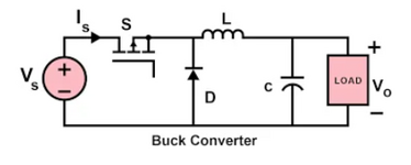
I am wondering about how we do the remote sensing in switch mode "buck converters". Is it possible to have remote sensing in switch mode buck converters.

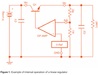
I understand the remote sensing concept when the load is far away from linear power supplies and how do we connect the sense wires in linear power supplies.

This post is about remote sensing in switch mode "buck converters".
 
Hi,

I guess you don´t like to read the following lines, because this is what I recommended quite frequently:

1) do an internet search on "remote sensing in power supplies"
2) read through some documents (not only one)
3) in case of missing informations: ask a detailed question by referencing to the document / page / chapter.

Klaus
 
I thing eg. some converter ic datasheets specify the layout specs and where to put the feedback for the regulator to be stable..so i would go and see there.. :)
 
Another factor is load capacitance. Suppose the disturbance is faster ( step load) than the error correction can respond. In that case, sensing adds delay or 1st order LPF pole in the simple case to an already higher order loop, which can cause more ripple than the resistive load drop. This requires an understanding of closed-loop servos and gain/phase margin.
 
Last edited:
I have attached the circuit of buck converter. I understand how this switch mode power supply works.

I don't see any error amplifier and pass element in the circuit.
 

Attachments

  • 172226799222688.png
    172226799222688.png
    25 KB · Views: 48
FET is the pass element
Gate is missing feedback, error amp and driver.
What is the voltage with no load ?
How does the impedance of the switch at %d.f. and X(L) at f ratio with load R affect voltage?
--- Updated ---

I have attached the circuit of buck converter. I understand how this switch mode power supply works.

I don't see any error amplifier and pass element in the circuit.
Neither do we see it because you have a very simple "open loop"
You may not be ready to understand SMPS until you know about servo control loops.

But if you are an expert car driver, try to read this.
 
Last edited:
Thanks for sharing this document. I will read and try to understand how error amplifier, feedback and pass element work in buck converter.
 
Start with the wiki References at the end.

This is a very advanced presentation on servo loops.

It will be too much unless you have studied below in 4th year perhaps.
1722544549067.png
 
Last edited:
Remote sense is about another loop - the "ground loop".

A problem with using remote sense to fix a ground loop / line drop problem is the lag it adds, a bad phase adder that forces loop BW lower (just what you don't want, even more inductive looking from the "client's" input point of view).

There's a big push into very high current and current-slew, low voltage supplies now and all this is being revisited hard.
 
Another factor is load capacitance. Suppose the disturbance is faster ( step load) than the error correction can respond. In that case, sensing adds delay or 1st order LPF pole in the simple case to an already higher order loop, which can cause more ripple than the resistive load drop. This requires an understanding of closed-loop servos and gain/phase margin.
This is an important point that if the current variation at the remote load is faster that causing variable voltage drop across long cables much faster and the error correction is slower. This can add sensing delays. and due to load capacitance and long wire resistance, the first order low pass filter will be established. The close loop gain and phase margin will then be associated.
--- Updated ---

FET is the pass element
Gate is missing feedback, error amp and driver.
What is the voltage with no load ?
How does the impedance of the switch at %d.f. and X(L) at f ratio with load R affect voltage?
--- Updated ---


Neither do we see it because you have a very simple "open loop"
You may not be ready to understand SMPS until you know about servo control loops.

But if you are an expert car driver, try to read this.

You mentioned that in my post #5, FET is pass element in the attached buck converter circuit, but the gate driver, feedback from output and error amplifier are missing in the circuit of buck converter in post #5.

I found a circuit (see attachment) in which pass element (Q1), error amplifier (OP AMP), voltage reference (V-REF) and negative feedback which is a voltage divider consisting of R1 and R2 are shown.

I understand how it works. So this part was missing in the circuit from post #5.

I am taking this at conceptual design level understanding without the actual specifications.

As the output drops below the set point. The mid-point of the voltage divider (connected at -ve input of error amplifier) also drops. As it drops below the V-REF (connected at +ve input of error amplifier), the output of error amplifier will turn high which will turn on the pass element. This will increase the output voltage level.

As the output voltage level increase beyond the set value, the mid point of the voltage divider is also increase and will become higher then V-REF, this will make the output of the error amplifier low. The pass element will turn off.

Now regarding the attachment of sense wire. I think the sense wires should run from the top of the upper voltage divider resistor to the point of load and the other wire should run from bottom of the lower voltage divider resistor to the point of load reference.

The ground of the V-REF should also be attached to the bottom of the lower voltage divider resistor.
 

Attachments

  • Untitled 752.png
    Untitled 752.png
    83.5 KB · Views: 38
Last edited:
I think ... and the other wire should run from bottom of the lower voltage divider resistor to the point of load reference.
"I think" is no good design partner.
Math could be. But you don´t use math, otherwise you would "know" that this is counter productive.

"I think" you will never change. Prove me wrong. ;-)

Klaus
 
Last edited:
To be honest, all it is , is that you have a volt drop in long cables to the load. So you use a diff amp to "bring" the remote vout to the local vout of the SMPS...then you dont get this problem of the cable drop being in the feedback loop.
 

LaTeX Commands Quick-Menu:

Similar threads

Part and Inventory Search

Welcome to EDABoard.com

Sponsor

Back
Top