neazoi
Advanced Member level 6

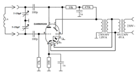
I have found on the internet this grid dip meter (pdf file) and I have converted it to a grid dip meter that uses self-rectification. I.e. it operates the tube only for a fraction of the time, when the anode voltage is sufficient. At other fractions the voltage is either negative or not sufficient and the tube cuts off or does not operate.
I have been introduced to self-rectification using this video
at around 13 mins.
Will my idea work?
Have I done any mistakes in the circuit (image file)?
Note that I am using a different tube, so I am not sure about it's pin 2 connection.
I have been introduced to self-rectification using this video
Will my idea work?
Have I done any mistakes in the circuit (image file)?
Note that I am using a different tube, so I am not sure about it's pin 2 connection.

