Continue to Site

Welcome to EDAboard.com

Welcome to our site! EDAboard.com is an international Electronics Discussion Forum focused on EDA software, circuits, schematics, books, theory, papers, asic, pld, 8051, DSP, Network, RF, Analog Design, PCB, Service Manuals... and a whole lot more! To participate you need to register. Registration is free. Click here to register now.

Selection of ICs, Transistors, Power Supply for Big 7-Seg (say 6 inch) for MCU

Status
Not open for further replies.

saramah

Member level 3
Member level 3
Joined
Apr 25, 2018
Messages
64
Helped
0
Reputation
0
Reaction score
0
Trophy points
6
Activity points
689
I done clock with RTC, MCU16F887 and the disp used there is 6 digit 7-seg of 1 inch each with Multiplexing.

1 inch ckt.png

>> Now I intend to use BIG like, 6" 7-SEG, 6 digit to disp the time instead of 1 inc.
The spec for 6" is below::
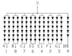
7SEG_CA.jpg

It is >CA,
each segment has > 6-row 2 column, If-20ma, Vf-12 volts.

>> I googled and find a ckt for 2.3" attached here,

View attachment 2.3 inch_CA_frm SDGeLECTRONICS.png

here used as Anode driver- ULN2003A (o/p current 500ma per driver pin) and BC327(collector current of 500mA) AND Cathod Driver- ULN2803(collectro current 500ma).
and Each Segments is of 4 RED LED in series, so forward voltage of the segments is 10v(approx).
Power supply for mcu is at 3.3 v used here.

>> Would you please suggest:
in my case-
1) can I use 12 v and 5 volt power supply
2) As Anode driver: can i use same ULN2003A and BC327:
3 As Cathode : can use ULN2803.

tnx
 

You can use a similar topology. I notice that YSD-1100AR7B-15 (I guess that's your LED display) is specified with only 30 mA segment peak current. Thus it's not well suited for multiplexing with larger digit count.

The display has forward voltage around 12 V, you need higher supply voltage, e.g. 15 V to achieve current regulation.

https://www.sparkfun.com/datasheets/Components/YSD-1600AR6F-89.pdf
 

HTML:
Thus it's not well suited for multiplexing with larger digit count.
tota30ma x 7 = 210 ma for each digit, then if i use ,
HTML:
Anode driver- ULN2003A (o/p current 500ma per driver pin) and BC327(collector current of 500mA) AND Cathod Driver- ULN2803(collectro current 500ma).

all will be coming under rating. then why not suited as u said.
Will u plaese update the fact ??
 

I notice that YSD-1100AR7B-15 (I guess that's your LED display) is specified with only 30 mA segment peak current. Thus it's not well suited for multiplexing with larger digit count.

Some old TI LED calculators multiplexed the other way around, they enabled one segment at a time for all digits.
The advantage is that the peak current is independent of the number of digits. The peak current is always 8 times the average current (with 7 segments + decimal point per digit) .
 

so , could you plase let me know, what and how would be the best suited way to use the large (6"/12") display to disp my case.
And for that what component will be suited for that.
tnx for reply..
 

HTML:
Thus it's not well suited for multiplexing with larger digit count.
tota30ma x 7 = 210 ma for each digit, then if i use ,
HTML:
Anode driver- ULN2003A (o/p current 500ma per driver pin) and BC327(collector current of 500mA) AND Cathod Driver- ULN2803(collectro current 500ma).

all will be coming under rating. then why not suited as u said.
Will u plaese update the fact ??[/QUOTE]
It will work just fine.
For a 6 digit clock, the average current in the LED's will only be 30 mA / 6 = 5 mA, but that is more than enough for modern LEDs.
According to the datasheet, the decimal point uses one string of LEDS, and all the other segments use two parallel strings.
I think this means that the peak current for the segments is 60 mA, 30 mA in each string.
The peak current for one digit is then 7*2*30 mA + 1 * 30 mA = 450 mA

You should have a series resistor for each segment driver to get a predictable current.Don't assume that you really need as high current as possible.
In this case you can easily make the current adjustable by making the 15V supply adjustable.
 
Last edited:

I see no indication that the current rating is meant per LED string. 5 mA average in x6 mux may be too low for bright ambient light conditions.

Thus I think, this display will be best operated in non-mux.
 

ok std, the series resistor for each segment (2 parallel string) will be 15v/60ma=250, standard 230R. And the total power consumption 450ma x 6 digit =2.7amps IF all are ON. That means 40.5 watage adaptor will be requred.
Pl correct me if i am wrong with the calculation.

@FVM::
Code:
I see no indication that the current rating is meant per LED string. 5 mA average in x6 mux may be too low for bright ambient light conditions. 

Thus I think, this display will be best operated in non-mux.
Will it be too dimmed at ambient light conditions?
Could u share a link for non-mux.
tnx all of u.
 

ok std, the series resistor for each segment (2 parallel string) will be 15v/60ma=250, standard 230R.
No, the voltage drop across the resistor should only be about 3V (15V - 12V). So 100 Ohms for 30 mA or 50 Ohms for 60 mA.
If you start vith a supply voltage and segment resistors that only give 20 mA you have a good test/debug setup. If the multiplexing fails no LEDs will be destroyed.
You will see the segments with 20 mA peak current. When the design works you can increase the peak current. This can be done by increasing the supply voltage a little.

I think that the multiplex solution is OK, but when you get the display you should first determine how much DC current is needed to give the wanted brightness.
Then you can decide if you want multiplex or not.

Unfortunately we are not sure about the maximum peak current in the segments.
The decimal point max peak current is easy since it only has one string of LEDs. However, it only has 5 series LEDs in the data sheet, so the forward voltage should be lower than 12V. You have to measure that.
The segments have 2 strings of LEDs, so the max peak current can be 30 mA or 60 mA. This is not a problem if you get enough ligfht with 5 mA since you can then use 30 mA peak current with 1/6 multiplex.
 

hello

hello,


ULN2803 + UDN2981 is a good pair of devices to drive 7 segm display.
**broken link removed**

if you have a Big display with 6 leds in serial to build one segment (Red color !)
you will loose about 6x1,5V=9V as direct forward voltage , and near 1V accross the driver Segm + driver Anode
with 12V as supply
to choose the serail resistor on each segment line
12 - 9 -1 = 2 V remaining voltage
with R=100 ohms
I seg= 2/ 100 ohms => ~20mA


with blue led, or white led , you can not use 12V only as power supply
6x 2,2=13,2V as forward voltage
=> go up to 15V or 18V
 

To see a clear and unambiguous datasheet of a large size seven segment display, review Kingbright SC40-19SRWA. It's e.g. accounting for different forward voltage and current rating of DP and other segments. As for YSD-1100AR7B-15, you'll either request the missing information from the vendor or make your own specification based on empirical tests.

https://www.kingbrightusa.com/images/catalog/SPEC/SC40-19SRWA.pdf
 

Hi,

Just like std_match, I believe the 30mA Ipf specification is for each individual LED and so same for all LEDs in a string. A good reason is that the decimal point has a single string.

Also consider that the 30mA was specified for 10% duty cycle at 10kHz as absolute maximum rating. I would use a lower Ipf for a design and would adjust accordingly to my frequency and duty cycle.
 

I did a similar project recently, except I used MOSFETs to both, sink and source, current. Have a look at the AO3400A (N Channel MOSFET, Min Vgs(th) = 1.05V, Max Id = 4.7A) and the AO3401A (P Channel MOSFET, Vgs(th) = -1V, Max Id = -4.3A). They are small, fast, cheap and robust.

Hope this helps.
 

Hi,

Or arrays like TPL7407..

Klaus
 

It will work just fine.
For a 6 digit clock, the average current in the LED's will only be 30 mA / 6 = 5 mA, but that is more than enough for modern LEDs.
According to the datasheet, the decimal point uses one string of LEDS, and all the other segments use two parallel strings.
I think this means that the peak current for the segments is 60 mA, 30 mA in each string.
The peak current for one digit is then 7*2*30 mA + 1 * 30 mA = 450 mA

You should have a series resistor for each segment driver to get a predictable current.Don't assume that you really need as high current as possible.
In this case you can easily make the current adjustable by making the 15V supply adjustable.

tnx std..
As a power supply unit to drive all the digits, I want my own unit which is combination of Bridge rect, Filter cap, ic LM7815 arrangement only.
But what should be transformer (for 230/15v) amp rating for driving all 6 digits:
will be that, 450 mA * 6 Digits = 2700 mA (+ additional 20%) = 3240 mA
So Should I need to use the TRF of MORE THAN 3240 mA for sec 15V. (as this CURRENT will not available at market, but with this calculation I want to drive 2 digits with 230/15v of 1000 mA only for testing purpose,

OR, 15V 4A SMPS - 60W - DC Metal Power Supply, and if not available in local market then should i
18V 4A SMPS - 72W - DC Metal Power Supply.

TNX..
 

If you are multiplexing the 6 digits, you only need a power supply big enough to drive one digit at the time, in this case 450mA depending on the segment current.
This is the whole idea with multiplexing, spreading the energy between each device in time.
For driving the displays and segments I would have used MOSFETs to have better control over the switching. ULN and UDN drivers are slow, and you may experience ghosting between digits.
For common anode displays, the anode drivers need 2 MOSFETs for each display, one NMOS and one PMOS plus a pullup resistor. The segment driver only need a NMOS and a resistor for the current adjustment.
 

Status
Not open for further replies.

Similar threads

Part and Inventory Search

Welcome to EDABoard.com

Sponsor

Back
Top