Continue to Site

Welcome to EDAboard.com

Welcome to our site! EDAboard.com is an international Electronics Discussion Forum focused on EDA software, circuits, schematics, books, theory, papers, asic, pld, 8051, DSP, Network, RF, Analog Design, PCB, Service Manuals... and a whole lot more! To participate you need to register. Registration is free. Click here to register now.

[SOLVED] selecting an IC buffer

Status
Not open for further replies.

dzakriel

Junior Member level 3
Joined
Oct 4, 2010
Messages
27
Helped
2
Reputation
4
Reaction score
2
Trophy points
1,283
Activity points
1,481
I need an IC buffer to keep the voltage from my micro high. When I program my micro to produce a high logic "1" (3.5-5v) I only get that much when i haven't connectt my micro to the device i need to control. because after i contact it to my device the voltage drop to the level 0.8-1.6V even i program it to produce 5V.

PLease give your advice, thank you.
 

Last edited:
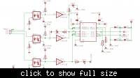
i'm sorry but i don't really get by your mean of "pulling too much current"? but some of my friends also recommend the ULN2003 maybe it will be more clear if I put my device sch right? here it is.


and i use a MCS51 or technically "AT89S51" so your link might be a little miss to the problem i have roght now.

but thank you very much for your respond. :)

---------- Post added at 17:36 ---------- Previous post was at 17:26 ----------

ah i'm sorry one more question. did ULN2003 can work with input 1.7V? this Voltage occur even when I connect my MCU pin to a LED Modul. (8 LED to visualyzed the 8bit data from MCU port/pin)
 

what is X1 and X2.is it a motor? if it is, then use proper motor driver IC instead of driving it directly from MCU.AT89S51 can provide max of 25mA current. if your motor current is more than that, loading is bound to happen. means, motor is driving more current than source capability. hence the MCU pin is getting loaded.
same is the case with LED module.:idea:
 
Sounds like you are trying to make a 8051 output port source current to the opto coupler. As you can read from the data sheet, they aren't intended for this operation, they are just open drain outputs with a weak pull-up. The most simple method would be to operate the output active low rather than active high. If you ever studied 8051 example cuircuits, you'll notice, that loads like LEDs or opto-couplers are usually driven this way. If the port's current capability still isn't sufficient (depends on your 8051 variant), I would add a discrete transistor to each LED driving output.
 
I read the datasheet of AT89S51, it is not very clear but i think the voltage drops rapidly when you try to pull current.
Maybe you could try to use inverted logic because output circuits usually can sink more current than they can source,
connect the output of the mc to the cathode and the anode to 5v (using a resistor ) so that you switch on when you have a logic 0 but I'm not sure if the mc will be able to output above 4v so that it can shutdown the diode, but you can still try it.

Alex
 
I read the datasheet of AT89S51, it is not very clear but i think the voltage drops rapidly when you try to pull current.
It's clearly in the 10 µA oder of magnitude. I checked, that P1-3 are guaranteed to sink 1.6 mA and P0 3.2 mA in active low state. There's also a specified maximum rating for port pins and port groups. This means, that you should better have external driver transistors to connect three opto couplers. But as said, you should operate them active low. ULN2803 also won't work without adding pull-up resistors at the ports.

P.S.: Another point to consider is the intended behaviour at chip reset. The default port state, which is always high with 8051, shouldn't drive the outputs unintentionally. This ususally leads to active low switching.

My switch transistor suggestion should be read as such: Have pnp transistors, e.g. BC557, connect them as follwers: base to port pin, collector to ground, emitter through series resistor to LED cathode, anode to +5V.
 
Last edited:
To FvM,

I have never used this kind of mc and i was writing my email while you posted your email so i said it was not clear because i was only seeing low µA currents in the test conditions and i was unclear what would happen when more current was pulled from the output.
It was all clear when you said that the output is open drain with a weak pull-up.

Alex
 
to:ppdr123 yes X1-1 and X1-2 is L298 output to the motor, this device design flow is like this, MCU give signal like ENable (Enable A and Enable B was connected to be one pin) and PWM for IN1/IN4; IN2/IN3;

to:FvM yes the MCU pin output goes to the opto coupler to drive L298. I afraid if I use a NOT for each OptoCoupler (before this IC right?) it will always at high logic wether I give signal or Not, since I also use a PWM that changes from high to Low then high again with some rythm...

---------- Post added at 18:42 ---------- Previous post was at 18:39 ----------

to:all i think I might be need to make a darlington module to amplify my MCU output in order mu device will work properly. will ULN2003 be the answer for this problem? what do all of you says?
 

all i think I might be need to make a darlington module to amplify my MCU output in order mu device will work properly. will ULN2003 be the answer for this problem? what do all of you says?

ULN2803 also won't work without adding pull-up resistors at the ports.

My switch transistor suggestion should be read as such: Have pnp transistors, e.g. BC557, connect them as follwers: base to port pin, collector to ground, emitter through series resistor to LED cathode, anode to +5V.

FvM has already answered to that (ULN2803, ULN2003) and has suggested a proper driver circuit.

Alex
 
Status
Not open for further replies.

Similar threads

Part and Inventory Search

Welcome to EDABoard.com

Sponsor

Back
Top