ljille
Member level 2

I'm in the process of designing a device and pretended to use a PIC 18f4550, in a way I could build 3 sinusoidal signals, 120 degrees delayed each, so it is a triphasic system at a frequency a little lower than 5,000 Hertz. (The instruction for hpwm in picbasic I didn't find the way to use it correctly) To make this, I thought I could vary the width of pulses (switching 3 pins and using a bridge to generate the negative part), but, if I need to control each cicle in 1/5000 Sec. and each cicle with at least 40 pulses to make 1 cicle of the wave, and each pulse could have 10 values of width on time, the minimal time unit would be about 500 nS, but I need a program of about 200 instructions (look for sensors, 3 ADs, ), so, I need about 40 mS for each program cicle. So in order to compare time with an 'interruptions made' clock, I'd need a clock 80 times faster than my original design with a 20 MHz clock: 1.6 GHz
So, in these order of ideas, I'm thinking in a redesign with a 1.8 GHz capable microcontroler. But then that is why I preffer to ask for help:
1. Is there a way of generating a 5,000 Hertz triphasic signal with the pic 18f4550, even if I add some peripheral devices?
2. If not, Is there a microcontroller capable of this PWM Speed or, for a program method, with a clock of 1,8 GHz? Is it expensive?
3. I use pic basic pro, I'd try to use same compilation method, unless it be impossible
4. Maybe there are some other devices than a uController, that are thought to generate this signals and I don't know them, but you could talk me about them
5. I saw in (https://www.microchip.com/forums/m819149.aspx) the next sentence: ""From a PIC24 CPU, I have a 3.3 Volt PWM output, modulated at 1 kHz using an 8-bit lookup table for the sine values. The PWM frequency is 32.768 kHz." this with on AN1523
6. I saw in ( https://www.microchip.com/forums/m1158178.aspx) the next phrase: "I see on the table at page 30 of the document DS61111E that when the peripherals are running at 50MHz I can get 234kHz with 7.7bit resolution which would be ok for my application." but I didn't find further information about it
Looking in MAPS I am considering PIC24FJ32MC104-I/PT because I saw that it can generate a fast PWM signal, but I see I ignore how they do it I have tryed to understand HPWM instruction in PicBasic Pro, which offer to use the PWM channel independently of the program, but, it is not clear to me how to follow the lookup table to get a sine kind wave. (If I had to use C or mikroC, I ignore if there is an analog function there) I have some questions about the final filter, but first if I just could generate the wanted 5,000 Hz signal with the 18f4550, it would be great.
I reviewed the AN900 document, but it is oriented to a system with retrofeed, but it is not clear for me how was generated the signal.
I did a lookup table, but I wonder what happen if each pulse I have to change the duty, the time between pulses is determined by the program, not by the HPWM, or I have not understood how it works. I want to make a stable frequency sinusoidal signal, repeated as a triphasic one. I have to tune it respect my physical system and then don't touch it any more. So the first question is the uProcessor, if I can use 18f4550 (even with a 48 MHz cristal, that I would get, because now I have a 18f4550 and the 20 MHz cristal) and how to achieve this 5 KHz, which seem very afordable comparing with the 6th point above.
If you had the patience of reading this, thank you, although you can't help me this time.
Thank you in advance and
best regards
Luis Jiménez I.
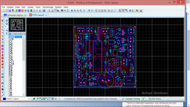
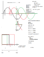
Attached the image of the 18f4550 circuit in proteus and a graphic idea of the signal


