pancho_hideboo
Advanced Member level 5

- Joined
- Oct 21, 2006
- Messages
- 2,847
- Helped
- 767
- Reputation
- 1,536
- Reaction score
- 733
- Trophy points
- 1,393
- Location
- Real Homeless
- Activity points
- 17,490
Follow along with the video below to see how to install our site as a web app on your home screen.
Note: This feature may not be available in some browsers.

Wrong.Some amount of input resistance must be present, for the structures to work.
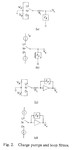
Do you understand charge pump type PLL surely ?So I said, why not try a simulation?
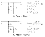
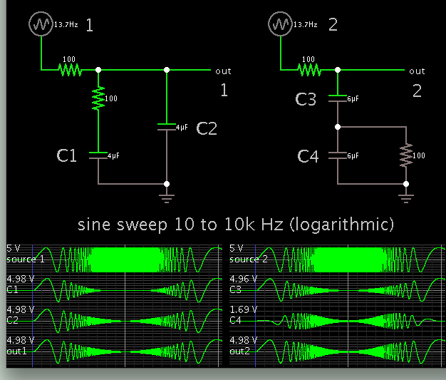
Your parameter's values give differerent transimpedance.To see the obvious manner in which their behavior might differ, a sine sweep is useful, to bring out their rolloff curve.
Completely irrelevant.Notice C1 has a sharper cutoff curve. C4 has a bandpass curve. These might serve some purpose for the PLL function, I don't know.
See #4 in this thread.The equations in post #1 clarify that both circuits are functionally equivalent, you can use one or the other.
So what's exactly the problem?