Continue to Site

Welcome to EDAboard.com

Welcome to our site! EDAboard.com is an international Electronics Discussion Forum focused on EDA software, circuits, schematics, books, theory, papers, asic, pld, 8051, DSP, Network, RF, Analog Design, PCB, Service Manuals... and a whole lot more! To participate you need to register. Registration is free. Click here to register now.

SCR gate triggering

bmandl

Full Member level 4
Full Member level 4
Joined
Feb 26, 2010
Messages
210
Helped
3
Reputation
6
Reaction score
3
Trophy points
1,298
Location
Slovenia
Activity points
3,006
So, I'm designing 3 phase motor soft starter for table saw with phase angle control with SCRs. I'll use 2 reverse parallel SCRs per phase (6 in total). Now, I'm unsure about gate triggering. I've build temp control for a 1 phase heater with TRIAC in the past. In that case, I used a DIAC based optocoupler and mains voltage for gate triggering. But in case of SCR, I'm not sure if I can do the same, or should I use VDD and transistor based optocoupler for gate firing? In latter case, wouldn't microcontroller be exposed if SCR fails and conducts between anode or cathode and gate?
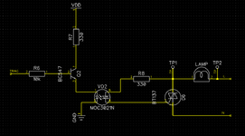
This is circuit, I used with TRIAC:
1727389364723.png


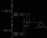
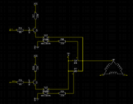
And this is what I'm thinking now for SCR - using same optocoupler and mains voltage (schematic is incomplete - just for one motor winding currently. TP1 is connected to L1):
1727392089574.png


So my question is: Can I use something like that, or should I use DC voltage for triggering gate of SCR? If so, what additional protection should I use for microcontroller in that case?
 

Attachments

  • 1727388866189.png
    1727388866189.png
    15.7 KB · Views: 40
  • 1727388914211.png
    1727388914211.png
    29.6 KB · Views: 55
  • 1727389412229.png
    1727389412229.png
    30.7 KB · Views: 50
Last edited:
I used a DIAC based optocoupler
are you sure? What part number is it?


or should I use VDD and transistor based optocoupler for gate firing? In latter case, wouldn't microcontroller be exposed if SCR fails and conducts between anode or cathode and gate?
1) if the SCR fails ... then there is something wrong with the design. In my designs I don´t consider parts to fail. SCRs are rather robust .. and if they fail, there surely is a reason.
2) you say you use an optocoupler ... this is an isolating part and thus you should not get a destroying feedback to the microcontroller

***
First big picture:
I don´t recommend the setup of Q2 as emitter follower. Emitter followeR is a circuit mainly used for linear circuits .. but here you clearly want a digital operation.
This does not mean that it does not work ... it just is rather unusual. Maybe you did this intentionally .. for a reason I don´t see.
(the same is true for all other pictures)

***
May I ask why you switched from TRIAC to SCR ... it makes things more difficult.

***
If so, what additional protection should I use for microcontroller in that case?
As already said: I design them to go not defective. And why should the SCR go defective, why not the microcontroller, the power suppy ... or anything else.

******
I´ve designed TRIAC control and SCR control. SCRs are used especially because of high power (250A/400V as well as 3000A RMS continously on a 1MW application 24/7)
There are 10 to 16 SCRs independently controlled. If the SCR get killed then there is a major problem else where. The microcontoller is the smaller problem.
In case of a bigger explosion you should consdier to replace the whole electronics including power supply, maybe even wiring.

Klaus
 
Thank you @KlausST for your answer.

are you sure? What part number is it?
Yes, I'm pretty sure. The part is MOC3021.

1) if the SCR fails ... then there is something wrong with the design. In my designs I don´t consider parts to fail. SCRs are rather robust .. and if they fail, there surely is a reason.
2) you say you use an optocoupler ... this is an isolating part and thus you should not get a destroying feedback to the microcontroller
I'm sorry, in the meantime I figured, that I indeed need an AC type of driving triac, better yet pulsing type - for reducing gate power dissipation. Not fully familiar with that concepts yet, but I'll investigate further.

***
First big picture:
I don´t recommend the setup of Q2 as emitter follower. Emitter followeR is a circuit mainly used for linear circuits .. but here you clearly want a digital operation.
This does not mean that it does not work ... it just is rather unusual. Maybe you did this intentionally .. for a reason I don´t see.
(the same is true for all other pictures)
Can you please explain why this circuit is not ideal in your opinion? Is the transistor I chose not ideal, or connection itself? What should I change? Oh, yes and it works in my other project, but I agree with you, if it works it does not mean it is the correct way to do it.

***
May I ask why you switched from TRIAC to SCR ... it makes things more difficult.

***
Somehow I got convinced by researching, that SCR is more appropriate for application like this, than TRIAC. By my understanding, TRIACs are more appropriate for applications like phase angle control for dimmers, heaters, etc, but for bigger loads like motor (in my case 5.5kW 3 phase motor), SCR is better option, especially because heat dissipation is divided among 2 devices instead of just on TRIAC. Maybe I'm wrong and I'd also be happier if that's true :)


But anyway, if I still insist by using SCRs after you explain to me, why this is unreasonable (just being hypothetical here), Is the circuit I draw (latter one) correct (ignoring emmiter follower part for now)? I should probably add some diodes for gate protection and perhaps some snubber circuit right?
 
Yes, I'm pretty sure. The part is MOC3021.
I can´t find any evidence for "DIAC"

AC type of driving triac, better yet pulsing type - for reducing gate power dissipation
Don´t know what this means. Please explain ... maybe draw a sketch...

Can you please explain why this circuit is not ideal in your opinion? Is the transistor I chose not ideal, or connection itself? What should I change? Oh, yes and it works in my other project, but I agree with you, if it works it does not mean it is the correct way to do it.
I clearly focussed on "emitter follower setup". If you are not familiar ... you are free to do an internet search on it.
The MOCxxxx datasheet shows the transistor connection. DS-70-99-0019, page #8 ... don´t forget the base resistor.

Your schematic neither says the voltage of VDD, nor the signal levels.
So I guess both are 3.3V (supplied)
If you get a base current of about 120uA ... Fairchild datasheet uses a ratio of 20 for switching applications...
So 120uA x 20 = 2.4mA only... while the datasheet talks about 8mA typ.
I would not be surprised if it causes some unexpected behaviour.
Did you CALCULATE your drive circuit? ... or where is it from?

but for bigger loads like motor (in my case 5.5kW 3 phase motor), SCR is better option, especially because heat dissipation is divided among 2 devices instead of just on TRIAC. Maybe I'm wrong and I'd also be happier if that's true
Again your information is missing mains voltage.
But for a 230V motor the line current may be about 10A.
Farnell lists about 400 TRIACS for >10A RMS. The package can handle the power dissipation and for the heatsink it does not matter at all.


But anyway, if I still insist by using SCRs after you explain to me, why this is unreasonable (just being hypothetical here), Is the circuit I draw (latter one) correct (ignoring emmiter follower part for now)? I should probably add some diodes for gate protection and perhaps some snubber circuit right?
The MOCxxxx datasheet tells you how to drive TRIACs. I would not be surprised if the MOC manufacturer provides documents how to drive SCRs.
Basically I´d add a diode in the gate drive path ... because the MOCxxxx device relies on the fact that the TRIAC switches ON when you drive the gate.
But an SCR only swithces on at one half wave. Now if you activate the MOC at the wrong half wave .. it may cause gate current, but the SCR does not switch ON ... causing overheat on the MOC.

Klaus
 
I can´t find any evidence for "DIAC"
TRIAC then? I thought output of optocoupler is just a DIAC device. Nevermind.

Don´t know what this means. Please explain ... maybe draw a sketch...
on this page: https://instrumentationtools.com/scr-triggering-methods/ under "Gate triggering" - AC gate triggering and Pulse gate triggering.

I clearly focussed on "emitter follower setup". If you are not familiar ... you are free to do an internet search on it.
The MOCxxxx datasheet shows the transistor connection. DS-70-99-0019, page #8 ... don´t forget the base resistor.
You mean this?
1727525892708.png

Ah yes, this is the case of typical transistor switch. Thanks I'll change that. And I should probably use UJT for pulsating triggering of SCR.


Your schematic neither says the voltage of VDD, nor the signal levels.
So I guess both are 3.3V (supplied)
If you get a base current of about 120uA ... Fairchild datasheet uses a ratio of 20 for switching applications...
So 120uA x 20 = 2.4mA only... while the datasheet talks about 8mA typ.
I would not be surprised if it causes some unexpected behaviour.
Did you CALCULATE your drive circuit? ... or where is it from?
Vdd is 5V.

Again your information is missing mains voltage.
But for a 230V motor the line current may be about 10A.
Farnell lists about 400 TRIACS for >10A RMS. The package can handle the power dissipation and for the heatsink it does not matter at all.
It's a 3 phase 400V 5.5kW motor. So RMS current is around 9-10A. I know there are a lot of TRIACs rated for such voltages and currents. I actually haven't found any real differences that would point to the fact that SCRs are used for higher currents and voltages. But I don't know why is it general belief that SCRs are more appropriate in motor soft starters than TRIACs. Perhaps I'm mistaken and I'd rather use TRIAC for sake of simplicity.


The MOCxxxx datasheet tells you how to drive TRIACs. I would not be surprised if the MOC manufacturer provides documents how to drive SCRs.
Basically I´d add a diode in the gate drive path ... because the MOCxxxx device relies on the fact that the TRIAC switches ON when you drive the gate.
But an SCR only swithces on at one half wave. Now if you activate the MOC at the wrong half wave .. it may cause gate current, but the SCR does not switch ON ... causing overheat on the MOC.
Good point, thanks!
 
TRIAC then? I thought output of optocoupler is just a DIAC device. Nevermind.
TRIAC is a three pin device. A controlled AC switch
DIAC is a two pin device .. I´d say a bidirectional tunnel diode

under "Gate triggering" - AC gate triggering and Pulse gate triggering.
OK. Understood.
But you are using a MOC. It simply triggers only until the TRIAC switched ON.
Using a MOC .. the gate power is automatically almost at minimum level.

Ah yes, this is the case of typical transistor switch. Thanks I'll change that. And I should probably use UJT for pulsating triggering of SCR.
Yes. The used BCxxx is good. Many others are good, too.
Again: you usually don´t use pulsed triggering with a MOCxxxx. You coud do .. but why?

Pulsed triggering is good if you use a pulse transformer. ... But I don´t see this here.

It's a 3 phase 400V 5.5kW motor. So RMS current is around 9-10A.
You have no inductive current? Pure ohmic?

I actually haven't found any real differences that would point to the fact that SCRs are used for higher currents and voltages.
I have not seen 3000A RMS triacs (maybe they exist) ... but SCRs...

But I don't know why is it general belief that SCRs are more appropriate in motor soft starters than TRIACs.
I don´t know either. Where is this information from? --> look up for more deatils.

Klaus
 
Since no gate pin is physically present, they use DIAC symbol but the gate is triggered by photo-electric current as a TRIAC.

I see no problem with your proposal.
1727534527935.png


If you are more confident with unipolar SCR switches, use them to avoid, 4 corner trigger issues in high power Triacs, yet it may not be necessary..

Otherwise, all you need are the polar ZCS triggers with a sweeping trigger advance using an analog or software method to reduce your typical 500 to 800% surge current to 100% or rated load to avoid heating your breaker to trip suddenly.

There may be other methods to soft start like using high-current ICLs
 
As stated, MOC3021 and similar devices are described as "opto-Triac".

You can basically use a SCR circuit as described in this thread https://www.edaboard.com/threads/back-to-back-scr-circuit.412269/
Pulse triggering is particularly advantageous in combination with trigger transformers or externally supplied trigger circuits. Opto-triac don't consume power after being triggered.

Part of SCR advantage, e.g. higher dV/dt immunity is however dwarted by using opto-Triac gate driver. You can still expect higher dI/dt and overcurrent rating.
 

LaTeX Commands Quick-Menu:

Similar threads

Part and Inventory Search

Welcome to EDABoard.com

Sponsor

Back
Top