Hi,
We have a 90-265VAC flyback for 20Vout and 1A.
It has a 47uF , 400V primary capacitor...as follows
EKXJ421ELL470MK35S
It also has a 50R NTC at the mains connector
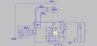
We are trying to assess the power dissipation in this NTC when at full load at 90VAC and 265VAC. We do this by putting a 0.6R sense resistor in the mains line so we can measure the mains input current to the SMPS. We also measure the voltage across the NTC.
Then we do V(NTC_peak)/I(mains) peak to find the NTC resistance (at that mains input voltage).
We then put such a resistance into the LTspice simulation and let LTspice do its power dissipation calculation.
The NTC voltage and the sense resistor are both measured with normal x10 probes. (obviously their ground clips are both connected to the same circuit node). The SMPS is fed via isolation transformer and variac.
We also scope the VAC mains input and the Primary HVDC bus capcaitor voltage..but these two measurements are done with diff probes.
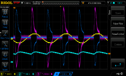
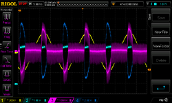
The scopes show...
Yellow = Mains VAC input
Light blue = Primary DC bus cap voltage
Red = 0.6R sense resistor voltage
Dark blue = NTC voltage.
Anyway, at 90VAC, the scope shots accord very closely with the LTspice simulation. (an NTC power dissipation of some 1.1W is seen).
However, at 265VAC input, the scope shots do not accord well with the LTspice simulation.
I believe i have accounted for capacitor ESR by adding it into the LTspice sim via ESR = DF x Xc.
Also, there is a small amount of mains flat-topping which is too small too account for the difference between LTspice and real thing.
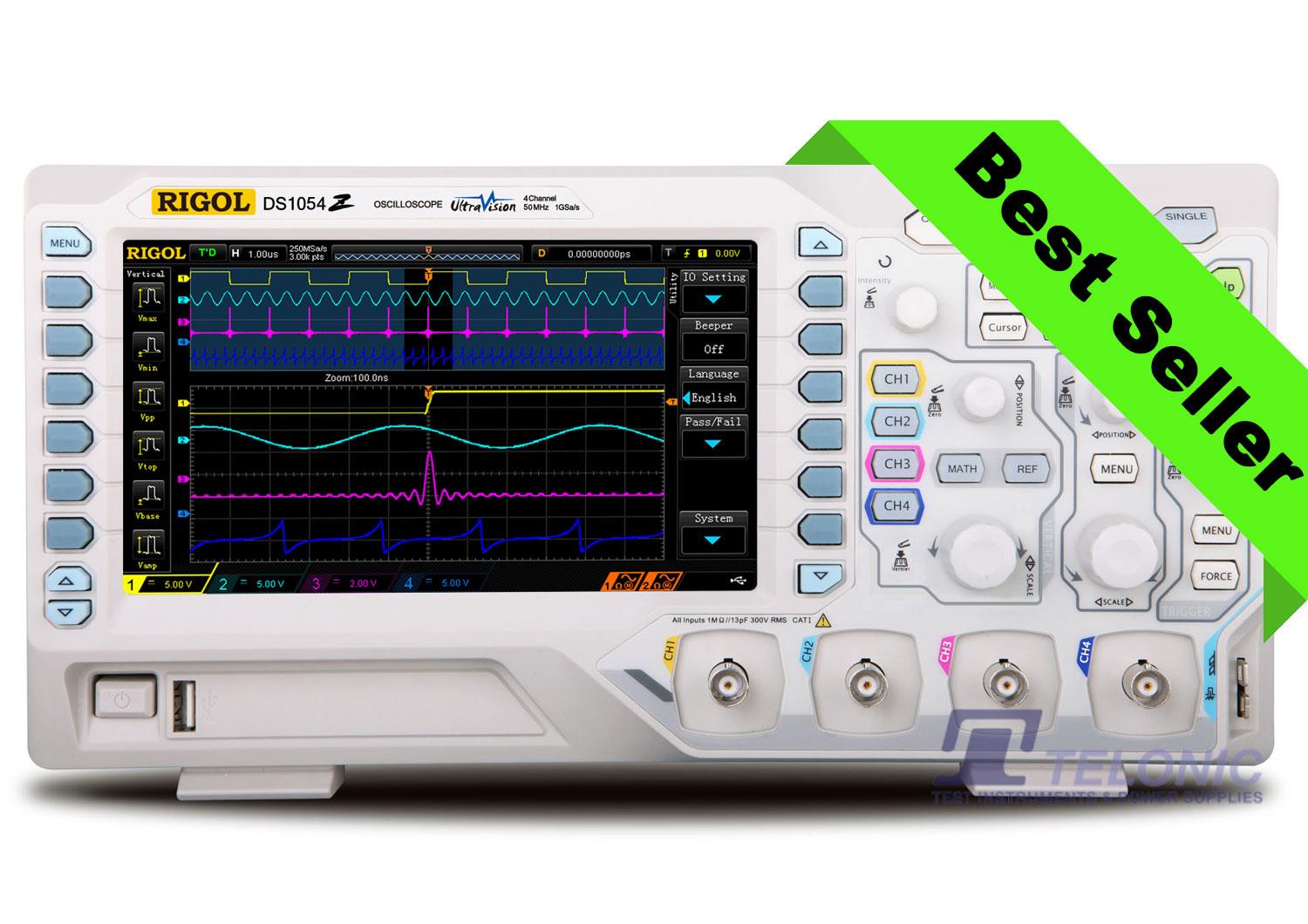
Anyway, i believe the large discrepancy at 265 VAC input is due to the common mode error in the scope probe measurement. Would you agree that this is the main cause of error? Its a Rigol DS1054Z oscilloscope...
Rigol DS1054Z
One of the most popular Rigol Oscilloscopes, provided by the leading Rigol distributer in the UK.

www.rigol-uk.co.uk


