pindiodemoradar
Newbie
Small background on myself:
Telecom Engineer with recent interest in microwave and RF circuit design. I am completely new to ADS.
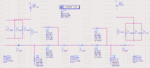
I was fascinated to see how PIN Diodes can be used as a switch in RF circuits. I decided to design and simulate one on ADS. The PIN Diode arrangement is in a hybrid combination. Very high isolation and fast switching speed are my goals. I chose Microsemi's MPP4203 (https://www.alldatasheet.com/datasheet-pdf/pdf/76506/MICROSEMI/MPP4203.html). 1GHz is the operating frequency. Upto 8GHz.
I have shared a screenshot of the design that I have come up with. But I am not getting the desired output. I tried multiple different values of L and C ranging from (pico to milli).
My issues:
1. I am not sure if I have used the correct PIN diode part in ADS.
2. Have I correctly typed the values from the datasheet to the PIN Diode part in ADS?
3. On simulation, how can I see the result of a positive bias and negative bias cycle in the graph window together?
I will really appreciate if the community can help me fix my issues and possibly give me concrete suggestions on how to get this circuit to work.")
Telecom Engineer with recent interest in microwave and RF circuit design. I am completely new to ADS.
I was fascinated to see how PIN Diodes can be used as a switch in RF circuits. I decided to design and simulate one on ADS. The PIN Diode arrangement is in a hybrid combination. Very high isolation and fast switching speed are my goals. I chose Microsemi's MPP4203 (https://www.alldatasheet.com/datasheet-pdf/pdf/76506/MICROSEMI/MPP4203.html). 1GHz is the operating frequency. Upto 8GHz.
I have shared a screenshot of the design that I have come up with. But I am not getting the desired output. I tried multiple different values of L and C ranging from (pico to milli).
My issues:
1. I am not sure if I have used the correct PIN diode part in ADS.
2. Have I correctly typed the values from the datasheet to the PIN Diode part in ADS?
3. On simulation, how can I see the result of a positive bias and negative bias cycle in the graph window together?
I will really appreciate if the community can help me fix my issues and possibly give me concrete suggestions on how to get this circuit to work.