Continue to Site

Welcome to EDAboard.com

Welcome to our site! EDAboard.com is an international Electronics Discussion Forum focused on EDA software, circuits, schematics, books, theory, papers, asic, pld, 8051, DSP, Network, RF, Analog Design, PCB, Service Manuals... and a whole lot more! To participate you need to register. Registration is free. Click here to register now.

SAW Sensor - Why is my circuit not oscillating?

Status
Not open for further replies.

saviobezerra

Newbie level 5
Newbie level 5
Joined
Apr 13, 2022
Messages
8
Helped
0
Reputation
0
Reaction score
0
Trophy points
1
Activity points
84
First, sorry for my bad english.

I'm building a project using a Colpitts Oscillator with Differential Pair, designed for ~117.6MHz. I'm using LTspice for simulation. The oscillator individually oscillates, but I need it to oscillate when I add a sensor model (as seen in the image in the circuit's feedback loop). When I add the sensor it initially wobbles and then stops, any ideas how I can fix this?
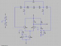
 

Attachments

  • circuit.jpg
    circuit.jpg
    150.8 KB · Views: 193

Hi,

On a quick view I see two issues:
* you probably overload the output with your "sensor". But this is just a guess, because we don't know anything about your sensor.
* a BC547 isn't really a HF transistor. It's gain at 117MHz is rather limited. Better try a more suitable HF transistor.

****
Hint for future forum posts:
When you already know that the problem relates to the sensor, it's necessary to give complete informations about the sensor.

Klaus
 

It's a project for the university, the feedback loop circuit is the model a sensor, which I can't change the values of any of its components. My project consists of building a colpitts oscillator with differential pair that works by adding the sensor to its feedback loop. The sensor has minimal insertion losses right at ~117.6MHz, so I designed the oscillator for that frequency. The oscillator works correctly without the sensor. But I have no more ideas on how to make the sensor work without changing the frequency.


About the BJT model, which one would you recommend?
 

I would say it needs an output buffer to isolate the sensor from directly influencing the oscillator. It may be a university project but in real life nobody would directly load an oscillator, at least a Colpitts one, without expecting it to influence frequency, amplitude or even stop it running.

Brian.
I understand that the attenuation will stop the circuit from oscillating, I'm looking for ideas on how to get around this problem.

Q1 is missing DC bias, so it's completely expectable to see no oscillations.


This is my circuit now, I switched the resistor position to the base of Q1. Still not oscillating, am I dc biasing correctly? any other suggestions?
 

Attachments

  • Sem título.png
    Sem título.png
    22.2 KB · Views: 152

Doubt that the circuit has sufficient loop gain. 500R 7.3pF is attenuating the signal, also 18p/1n divider.
 

I don't think that C2 is helping you, It is in the feed back loop and shorting the signal to ground.
When designing an oscillator try breaking the feedback loop and checking that there is some gain and that the phase is 360 degrees at the frequency you want.
A better transistor that is included in LTSpice would be 2N2369, it has an ft of 500MHz instead of 300, There may be better ones.
 

Simulation circuit is using UIC option, usually sufficient as initial kick start. Also the description in post #1 sounds like dying-out oscillation, oscillation condition not fulfilled. We might check the circuit if we have the LTspice files.
 

You can use the sim to reveal the node V's for bias setting to see if
your choices make sense.


Regards, Dana.
 

Simulation circuit is using UIC option, usually sufficient as initial kick start. Also the description in post #1 sounds like dying-out oscillation, oscillation condition not fulfilled. We might check the circuit if we have the LTspice files.
 

Attachments

  • Colpitts_117M_AC.rar
    966 bytes · Views: 124

As guessed, the loop gain is too low to maintain oscillations. A quick check that the topology can basically work as oscillator:

View attachment 175475
How did you calculate the parameters so that the circuit kept oscillating? In my case, I cannot change the values of the sensor components. This is my main "problem", I understand that when placing the sensor the Berkhausen criteria are no longer met, but I can't see which components of my Colpitts/differential amplifier I change to compensate for this.


Again, sorry for my English, in most of these sentences I'm using google translator
 

I didn't calculate anything, just arbitrarily modified component values to show that the topology can oscillate.

You apparently added the filter to a working oscillator without thinking about necessary circuit modifications. The filter has a voltage gain of -14 dB if driven by a low impedance source respectivel -20 dB power gain with matched impedance. Additional gain loss is caused by loading the original oscillator circuit.

Plotting the filter transfer function separately shows 180° phase shift in resonance, respectively the oscillator should use an inverting amplifier. A single CE stage seems to provide insufficient voltage gain, thus I tried a cascode circuit.

1650106891732.png
 

Attachments

  • Osc.zip
    1.7 KB · Views: 123
I didn't calculate anything, just arbitrarily modified component values to show that the topology can oscillate.

You apparently added the filter to a working oscillator without thinking about necessary circuit modifications. The filter has a voltage gain of -14 dB if driven by a low impedance source respectivel -20 dB power gain with matched impedance. Additional gain loss is caused by loading the original oscillator circuit.

Plotting the filter transfer function separately shows 180° phase shift in resonance, respectively the oscillator should use an inverting amplifier. A single CE stage seems to provide insufficient voltage gain, thus I tried a cascode circuit.

View attachment 175503
In the case of my first circuit, with the differential pair, where should I add the components that compensate for the loss in dB and the phase correction? At the output of the circuit (Vout)? Or in the feedback loop that goes to the sensor?
 

Attachments

  • Sem título2.png
    Sem título2.png
    12.9 KB · Views: 127

Try placing a wire connecting Q2 Q3 emitters to the join of C1 C2, as is usually done.

This Colpitts topology has current flowing forward and reverse through the supply. Your long-tail section needs to allow for this.
 

In the case of my first circuit, with the differential pair, where should I add the components that compensate for the loss in dB and the phase correction? At the output of the circuit (Vout)? Or in the feedback loop that goes to the sensor?
As stated above, about 180° degree phase shift of the sensor in resonance suggests an inverting amplifier, similar to a crystal oscillator. An inverting amplifier could be used with an inverting tank circuit, e.g. tapped inductor.
 

First, sorry for the bad english.
It's not the first time I've been looking for help on this circuit on the forum.
I'm from Brazil, I'm doing a university project using which basically consists of using a colpitts oscillator with differential pair, with a SAW sensor in its feedback loop. The SAW sensor has a frequency of 117MHz, and minimal insertion losses of ~-31dB. The challenge lies in designing the oscillator so that the gain compensates for the sensor losses. The SAW sensor model for Spice was used from another work (a master's thesis).

I managed to get my Colpitts Oscillator with differential pair oscillating at ~117MHz, but when I add the SAW the oscillation stops.

I'm not able to identify where exactly is the error of my circuit. Whether it's in the SAW model or my oscillator.
I would like any kind of help, be it articles or basic observations about my circuit.

Attached, I will put the images of the models used along with my SPICE file.

Thanks.

circuito.png


Sensor.png
Perdas.png
 

Attachments

  • ParDiferencial_SAW_150622.rar
    963 bytes · Views: 100

Status
Not open for further replies.

Similar threads

Part and Inventory Search

Welcome to EDABoard.com

Sponsor

Back
Top