Continue to Site

Welcome to EDAboard.com

Welcome to our site! EDAboard.com is an international Electronics Discussion Forum focused on EDA software, circuits, schematics, books, theory, papers, asic, pld, 8051, DSP, Network, RF, Analog Design, PCB, Service Manuals... and a whole lot more! To participate you need to register. Registration is free. Click here to register now.

Save max voltage to FET gates

Status
Not open for further replies.

boylesg

Advanced Member level 4
Joined
Jul 15, 2012
Messages
1,023
Helped
5
Reputation
10
Reaction score
6
Trophy points
1,318
Location
Epping, Victoria, Australia
Activity points
11,697
After my bad experiences with the falsely (in my view) quoted maximum voltage for TC4422 I thought I should check that the safe continuous max voltage quoted for FET gates is actually safe?

Or will also more than likely destroy the FET if you try it?

What if I was to apply 17V to a FET gate on a continuous basis? Would I be in safe territory or should I lower the voltage?
 

Hi,

You'd have to post the datasheet for the device you're talking about, otherwise answers are just rules of thumb and/or guessing.
 

Manufacturers are pretty careful about specifying the
conditions upon which their ratings are based. Lawyer-
like, quite often.

Abs Max is not that rating. It's the voltage where they
will no longer give one single damn about your whining
when it blows up (and it will before long).

Rec Max is where they guarantee reliable operation
(given whatever other constraints they may impose).

Rec Max plus one transient you don't happen to see,
and she goes boom anyway.

Your gate drive voltage maximum applied has no reason
to go past the point of diminishing returns on on
resistance. 17V is well past that for almost any power
MOSFET (other than crappy silicon carbide ones).
 

Hi,

You'd have to post the datasheet for the device you're talking about, otherwise answers are just rules of thumb and/or guessing.
View attachment FET IXTK62N25.pdf

All FET datasheets seem to have the same value for max gate voltage in the absolute maximums table......at least all the ones I have read to date.

- - - Updated - - -

Manufacturers are pretty careful about specifying the
conditions upon which their ratings are based. Lawyer-
like, quite often.

Abs Max is not that rating. It's the voltage where they
will no longer give one single damn about your whining
when it blows up (and it will before long).

Rec Max is where they guarantee reliable operation
(given whatever other constraints they may impose).

Rec Max plus one transient you don't happen to see,
and she goes boom anyway.

Your gate drive voltage maximum applied has no reason
to go past the point of diminishing returns on on
resistance. 17V is well past that for almost any power
MOSFET (other than crappy silicon carbide ones).

OK then!

1) I do not have an electrical engineering degree and have not been formally instructed on the nuances of datasheets.
2) I can't read the mind of the manufactures who wrote the datasheet.

So if 20V continuous on the gate will destroy the device, and 17V is still not a safe limit, then what is the safe maximum voltage for the gate of this FET?

Where do I find this bit of information if not in the datasheet?
 
Last edited:

Hi,

Without too much technical skill to back up the remark(s): Datasheet will have inscrutable and contradictory looking graphs and specs in table form, by reading them and comparing a bit, should be able to figure out if part looks like it can provide needed conditions for a circuit, and the frequent comparison - how many things you own do you push to the max.? Presumably none, that way things last and don't burn out/up, you need to derate a bit with everything.

Graphs may clarify, as post #3 stated, what voltage fully turns on device, etc.
There are no graphs in this datasheet so I an afraid your suggestion is no help in this instance. Still have no clear idea of what is a safe maximum voltage for a FET gate.

Update...I obtained a copy of the datasheet with the graphs in it - I must have picked up a truncated version of the datasheet originally.
 
Last edited:

Hi,

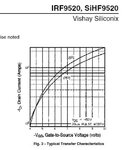
That datasheet is quite minimalist... Not a "same" part, but to show the general idea, hopefully, the IRF9520 datasheet provides a lot more info. to gauge what voltage you'd actually need on the gate for x Amps. The graph below is one way (/one part) of figuring out what's actually needed (and probably still getting it wrong, in my case).

vgsth 9520.JPG

Maybe reading some more generalised documentation about MOSFET theory of operation and/or device design could be helpful to establish rules of thumb to know what is and isn't needed?

Perhaps thinking of a MOSFET as sort of like a BJT that needs a minimum voltage and current to operate, and a few volts more for higher currents, but not necessarily the full supply rail voltage could be a helpful approach. Or the dreaded faucet/tap analogy...

- - - Updated - - -

Derate, it it says 17V max. then be circumspect and go a little lower, at a guess 10 to 15V may be amply sufficient most of the time. Max. is "do not go there" area for any part. And pulsed specifications are for micro- and millisecond amounts of time. I may be wrong, but Ohm's law probably can give some idea if the intention is unrealistic r.e. PD.
 

Attachments

  • Mosfet IRF9520 Vishay.pdf
    765.6 KB · Views: 74

Hi,

That datasheet is quite minimalist... Not a "same" part, but to show the general idea, hopefully, the IRF9520 datasheet provides a lot more info. to gauge what voltage you'd actually need on the gate for x Amps. The graph below is one way (/one part) of figuring out what's actually needed (and probably still getting it wrong, in my case)

Maybe reading some more generalised documentation about MOSFET theory of operation and/or device design could be helpful to establish rules of thumb to know what is and isn't needed?

Perhaps thinking of a MOSFET as sort of like a BJT that needs a minimum voltage and current to operate, and a few volts more for higher currents, but not necessarily the full supply rail voltage could be a helpful approach. Or the dreaded faucet/tap analogy...

- - - Updated - - -

Derate, it it says 17V max. then be circumspect and go a little lower, at a guess 10 to 15V may be amply sufficient most of the time. Max. is "do not go there" area for any part. And pulsed specifications are for micro- and millisecond amounts of time. I may be wrong, but Ohm's law probably can give some idea if the intention is unrealistic r.e. PD.

As previously stated I found a copy of the datasheet with the tables in it and after a little more googling it appears that 15V might be a reasonable safe max voltage.
 

Status
Not open for further replies.

Part and Inventory Search

Welcome to EDABoard.com

Sponsor

Back
Top