Continue to Site

Welcome to EDAboard.com

Welcome to our site! EDAboard.com is an international Electronics Discussion Forum focused on EDA software, circuits, schematics, books, theory, papers, asic, pld, 8051, DSP, Network, RF, Analog Design, PCB, Service Manuals... and a whole lot more! To participate you need to register. Registration is free. Click here to register now.

Saturation Current

Status
Not open for further replies.

vathsal

Newbie
Newbie level 3
Joined
Nov 5, 2022
Messages
3
Helped
0
Reputation
0
Reaction score
0
Trophy points
1
Activity points
44
Hi ,

I am designing a Fly-back converter i had calculated most of the components but i am having some doubt. I am having following data

Primary Peak current = 1.6 A
Secondary Current = 9 A

should my primary inductor saturation should be more than 1.6 A to be operated in full load.
 

The flux reaches a magnetic strength calculated as L * A (in Webers). Sufficient metal mass is needed so as to support this flux intensity. Suppose you test it by sending 1.6 Amperes through the primary, then see how many Amps you get from the primary through a low ohm load as the flux collapses. If you measure output much less than 1.6 A, then saturation rating is inadequate. A certain amount of loss is normal, say 15%.

Flux builds during the first half of the cycle in a flyback, then collapses during the second half. Your secondary delivers greater Amperes because the existing flux collapses quickly. Conditions of inductance and resistance can be arranged so this happens. The Weber figure itself doesn't change.
so i need to send 1.6 A through primary and check across low ohm resistance (across ground and source of mosfet ) it should show reading of 1.6 A say for instance if i have low ohm resistance of 0.2 ohm then on passing 1.6 A switching them at particular frequency then i should measure 0.32 v across the low ohm resistance.

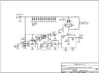
Please look below i have test model circuit which i found online instead of NE555 i am using signal generator. other than the setup is similar.

Am i right....?
 

Attachments

  • LMETER.png
    LMETER.png
    26.7 KB · Views: 141

Hold everything... There's a risk to doing this test with a transformer. When current is flowing in an inductor, and you abruptly shut it off, it generates an inductive kick. It's a current surge that needs to go somewhere. It may manifest as a high voltage spike. Or even arcing.

That is why a freewheeling diode is recommended across inductors which are operated in switching circuits.

When current is abruptly shut off in a transformer, It may cause inductive kick in other windings. A spark may jump between wires and leave a weld joining the wires. This becomes a short-circuit in one or more windings. The transformer becomes useless and may be unrepairable.

It looks as though we need a different approach. Inductors and transformers are prone to unexpected behavior. Experts gauge power capabilities by the transformer's weight and cross-section area. To take a measurement of the saturation rating shall require some ingenuity and effort.
 

should my primary inductor saturation should be more than 1.6 A to be operated in full load
Yes. Saturation can be best detected by observing the current waveform, as planned with your test circuit. At saturation point, the linear rising current will start to rise faster, changing to an exponential waveform.

Your test circuit absolutely needs a freewheeling circuit to avoid discharging of the stored energy in MOSFET avalanche breakdown. It should allow inductor current returning to zero before starting the next pulse.
 

Hold everything... There's a risk to doing this test with a transformer. When current is flowing in an inductor, and you abruptly shut it off, it generates an inductive kick. It's a current surge that needs to go somewhere. It may manifest as a high voltage spike. Or even arcing.

That is why a freewheeling diode is recommended across inductors which are operated in switching circuits.

When current is abruptly shut off in a transformer, It may cause inductive kick in other windings. A spark may jump between wires and leave a weld joining the wires. This becomes a short-circuit in one or more windings. The transformer becomes useless and may be unrepairable.

It looks as though we need a different approach. Inductors and transformers are prone to unexpected behavior. Experts gauge power capabilities by the transformer's weight and cross-section area. To take a measurement of the saturation rating shall require some ingenuity and effort.
yeah you are right i forgot that this is sample image i took some where from internet yeah will add free wheel diode and test it will tell you or show you the results
 

Status
Not open for further replies.

Similar threads

Part and Inventory Search

Welcome to EDABoard.com

Sponsor

Back
Top