Vermes
Advanced Member level 4


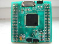
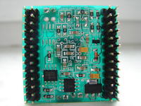
It is a system of mini module SAM3S4B with microcontroller Atmel ATSAM3S4B. The reason why those components were used is that the microcontroller has core Cortex M3, which is pin-compatible with AT91SAM7S256. It means that you can change your microcontroller with another core to more modern one without the need to change your PCB. Although, there are some minor differences between pins of AT91SAM7S and ATSAM3S. What more, you can change the microcontroller only in those circuits, where the processor does not work with 5V logic. When you want to change the microcontroller in a circuit with 5V logic, you have to process the circuit and the PCB, because I/O lines of the microcontroller SAM3S4B are not 5V tolerant. You also have to adapt the firmware of your device to work with new microcontroller.
Core Cortex M3 is more efficient and energy saving than for example ARM7TDMI. One of the assumption of this project was also to create a mini module, which fits board EVBsam7s. There are some changes in the module due to the fact, that pins of AT91SAM7S and ATSAM3S are quite different.
Below there are some of those changes:
- adding pins PB13 (pin No 59) and PB14 (63) to additional HEADER bar on mini module SAM3S4B. In microcontroller AT91SAM7S256, pin No 59 is VddFlash supply and commonly it is shorted with pin 58 VddIO. After changing the microcontroller to SAM3S4B in the application, pin PB13 is shorted with the supply. When you reset the microcontroller, all I/O lines are configured as inputs, so there should be no problems, except that the line PB13 will not be available. Pin 63 in AT91SAM7S256 is the output of RC filter, after change to ATSAM3S4B and soldering out RC components connected to that pin, it receives additional line PB14.
- change of DataFlash memory AT45DB321C in housing TSOP-28 to memory AT45DB321D in housing SO-8. It is recommended to use AT45DB321D in new application instead of AT45DB321C, although in this system this memory is not mounted, but there is a space for the PCB.
- additional memory: EEPROM SPI 25AA160 and RAM SPI 23K256, both in housings SO-8.
- deriving CS pins of those memories to configuration jumpers marked: Enable Flash, Enable RAM and Enable EEPROM. When the jumpers are on, CS lines of those memories are connected to the microcontroller. When the jumpers are taken off, CS lines of those memories are pulled up to +3,3V, which sets the SO outputs of those memories in high impedance state. This allows the selection of memories needed, depending on application requirements.
- applying easier available stabilizer LDO 3,3V (LD1117S33 type) of greater current efficiency.
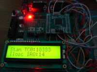
In attachment to the original thread of the project, you can find sample programs which show the way to configure some peripherals of the microcontroller. Those programs were written in IDE Rowley Crossworks for ARM ver 2.0.11. One of the pictures below shows operating boot board EVBsam7s with installed mini module SAM3S4B. In the attachment there is also a processed file SAM3S_Configure.S, which is attached by CrossWorks to every project. The processing allows you to select the clock for the core by right setting the register CKGR_MOR.
Pictures:


Link to original thread (useful attachment) - Minimoduł SAM3S4B do płyty uruchomieniowej EVBsam7s