Vermes
Advanced Member level 4

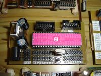
It is a design of runtime board for Atmega16/32, version DIP40. Previous version of the board, in the picture below, did not work correctly and this was the purpose why the new, etched board presented in this thread, was created.
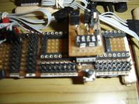
Picture of previous version:
Assumptions of the design:
- output of each of the pins from all ports (A, B, C, D) is double and in the same order
- output of SPI programming interface (Kanda) and JTAG
- possibility to exchange the quartz crystal
- possibility to supply from an external source of supply (DC plug + stabilizer 7805)
- output of the few mass connectors, voltage, before the stabilizer (12V), voltage past the stabilizer (5V)
- diode indicating switched on circuit
- button allowing the circuit reset
- fit in one side with the smallest number of through holes possible
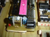
Pictures of the board:

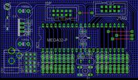
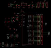
Eagle:
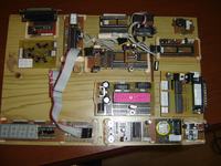
And last picture of the whole together with the set that can be home made:
Link to original thread (useful attachment) - Płytka uruchomieniowa pod Atmegę 16/32 wersja DIP40