Vermes
Advanced Member level 4


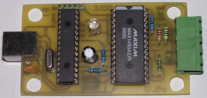
The system consists of two components: processor PIC18F2455 and circuit MAX1480.
MAX1480 has fully optocoupled interface for RS485, additionally reinforced by transils. On 5-pin connector there are doubled signals, so if the polarization RS485 is faulty, you can move the plug and change lines of the bus. Applying the processor made it possible to add few features to the device.
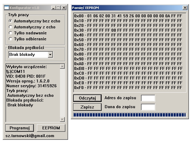
Additional options in special mode:
- access to the configuration, change the mode, block the speed
- access to EEPROM memory, it is possible to make something similar to a simple hardware key (240 bytes)
- access to a simple logic analyzer
Operation of the system is indicated by RGB diode, which indicates:
- red – power ok, without USB initialization
- green – the device is ready in the converter mode
- green + blue blinks – transmitting
- green + red blinks – receiving
- alternately blinking red and blue – special mode
- blue + red – analyzer mode running
- blue – analyzer ready to work
The resolultion of analyzer is in the range of approximately 83ns, provided that it is not able to distinguish such a rapid series of pulses. Real sampling reaches 1us. Application of the analyzer allows you to enlarge, move and use cursors. Functions of cursors can find slopes of the signals and calculate different values.
Transmission speed of the converter system is limited to the possible values in processor UART module settings.
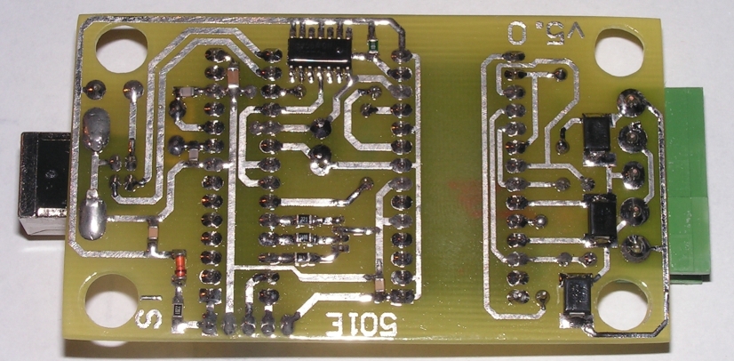
There are some pictures below of how it looks like and how the programs work.
Link to original thread (useful attachment) – Konwerter RS485 - USB z bajerami.