Continue to Site

Welcome to EDAboard.com

Welcome to our site! EDAboard.com is an international Electronics Discussion Forum focused on EDA software, circuits, schematics, books, theory, papers, asic, pld, 8051, DSP, Network, RF, Analog Design, PCB, Service Manuals... and a whole lot more! To participate you need to register. Registration is free. Click here to register now.

[SOLVED] RS232 Communication problem ad PCB design issues

Status
Not open for further replies.

elPresidente

Junior Member level 2
Joined
Jul 27, 2012
Messages
20
Helped
0
Reputation
0
Reaction score
0
Trophy points
1,281
Activity points
1,476
Hallo,
I've designed some electronic device based on PIC16F877A microcontroller and communicating with PC through USART-RS232 interface. The problem is it doesn't work properly. When i was designing this device I was doing it on breadboard using parts in DIL cases but now i moved everything to tiny SMD packages. During designing on breadboard computer could easily communicate with uC through HIN232 (MAX232 replacement) but now when i soldered it on PCB it doesn't work. It sometimes connect with device but then I can't send further commands because device stop to respond.
So i wonder if the problem could be wrong designed wires or ground planes on PCB, I'm very beginner in PCB designing and electronics. This is my first project. I thought also that these could be capacitors which are 100nF 0805 SMD and I was always using electrolytic 100nF THT with MAX/HIN232.

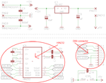
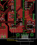
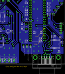
I put four images with schemes and pcb design to show You how it looks.
Please, give me some suggestions what I did wrong.
 
Last edited:

1) No images
2) Did you verify that the 232 chip is producing the expected positive and negative voltages? (This would tell you if the internal charge pumps are working properly). Look at pins 2 and 6.
3) Have you looked at your signals with an oscilloscope?
4) How do you know the problem is the 232 interface, and not something with
a) the processor?
b) your power supply?
c) your crystal or oscillator?
 

@barry
Thanks for reply

1) I meant those schemes and PCB design i put here.
2) V+ gives about +6V, V- -6V
I use both USB to COM (TTL levels) adapter - Prolific and real serial com port with +/-12V.

3) I don't have osc., only logic analyzer (I will test signal on digital side of HIN232)

4)Ok, I think that problem is with rs232 because i observed it before when all parts were on breadboard connected with each other by wires. When wires were short and there were only few ones connection was stable, when i used many wires and path from point to point was done by more than one wire suddenly connection was unstable and device not responded or was working in unstable way. So... i thought that after soldering the problem has the same nature (something with electric connections), maybe i am wrong.
a) I have a diode connected to processor's IO Port which informs that program started and configured all peripherals, that means that processors works properly.
b) Power supply is ok.
c) Don't know how to check Quartz resonator without oscilloscope, but i think it works, it worked for months, i have also replacements. Capacitors to quartz resonator have values like those in documentation.

My main concern is about rs232 connection stability. I have problem with that issue from the beginning of my dealing with electronics. It is often unstable, then for a moment it is stable and then again unstable. As i wrote before I think i solved this issue by using fewer number of shorter wires on breadboard and it passed exam. I don't know the reason of this instability, maybe too much electric wires' capacitance. But on PCB i don't know what pitfalls i should avoid to make it reliable.
 

You SAID it worked fine on the breadboard, and DIDN'T work on the circuit board. Now you've changed your story and said it didn't work reliably on the breadboard either.

I think you need an oscilloscope to verify that your signals are ok. Also, verify that you've got your communication parameters (baud rate, parity, etc.) set properly. Try, if you can, running at a lower baud rate to see if that makes it more reliable.
 

Yeah, you are right, In the beginning i didn't mention about initial problems with breadboard (thinking it is not important to talk about, after all it started to work on the breadboard) and then I explained the whole story.

The problem occurs not matter what baud rate i set, i start always connecting with device from 9600 kbps and then it switch on specific baudrate. Such things as parity, number of stop bits, etc. are fixed.

So will have to see signals on oscilloscope when i find one.

Could this problem be related with something with ground plane (maybe noise from quartz oscillator or diodes currents)? Wrong capacitors (not electrolytic)?

I don't know if you saw those images so i put it once again.
 

Attachments

  • 1 - uC.png
    1 - uC.png
    34 KB · Views: 128
  • 2 - RS232.png
    2 - RS232.png
    25.9 KB · Views: 130
  • 3 - PCB - Top.png
    3 - PCB - Top.png
    61.6 KB · Views: 118
  • 4 - PCB - Bottom.png
    4 - PCB - Bottom.png
    63.7 KB · Views: 119
Last edited:

RS-232 uses pretty high voltages (+/- 3v, min) so it's relatively impervious to noise (at least as far as the things you mentioned). Are you seeing ANY data at all? If it was a noise problem, you'd see occasional bad data,not zero data.
 

Yes, i can connect to device from PC - it means that data is send from PC to device, then resend back to PC and checked if was good or not. But not always it works, sometimes it is stuck in the middle and device doesn't resend data. After connecting i want to start measurement (device is intended to measuring voltages through ADC) and device doesn't respond EVER while when i had it on breadboard it responded. It behaves like that. I couldn't check it by logic analyzer, i will do it later.
 

It's pretty hard to debug this without looking at signals, and/or having a debugger running in the PIC. There's no way to know where the problem is; maybe hardware, maybe software, maybe both.
 

Yes, i resolder it again in couple of days, see if problem occurs and if yes i will try to examine signals. I'll be probably back in 4-5 days. Thanks for suggestions.
 

I'm ashamed to admit it but problem was in part in software. Sorry for wasting your time.
 

Status
Not open for further replies.

Similar threads

Part and Inventory Search

Welcome to EDABoard.com

Sponsor

Back
Top