xeroshady
Newbie level 3

hey guys, I'm a first year college student, and need help designing a circuit for a mini project. I'm a total newbie when it comes to electronics, so please forgive me if my questions are stupid.
I'm planning to make a solar powered clock, which works as follows:
-> when sunlight falls directly on the solar panel, and the voltage produced by it is maximum, the solar panel will power a set of rechargeable batteries and a clock
-> when the sun moves (or rather, the earth rotates), and the intensity of light falling on the panel reduces, the panel should get disconnected from the circuit, and the rechargeable batteries should power the clock, and a motor
-> the motor makes the whole setup rotate, until the solar panel receives sunlight of maximum intensity again. At this point, the rechargeable batteries should stop supplying power to both the motor and the clock, and the solar panel should take over, supplying current to the rechargeable batteries and the clock
-> the process should continue till the evening when no light falls on the solar panel, and at this point, the motor should stop rotating (not sure if this concept even sounds plausible)
Instead of connecting the motor to the main circuit, should I connect it to a photo transistor in a separate circuit? will that work?
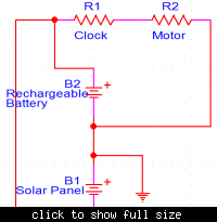
I've attached a sample circuit, I'm not even sure if it is right. It's missing transistors which act as switches and control the current flow. I have no idea where and how to place them. Can you guys help me out with the circuit, and give me some advice regarding the basic concept of this project (feasibility, problems I might encounter, etc.)?


