Vermes
Advanced Member level 4

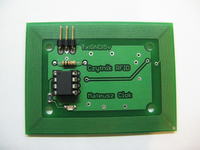
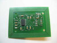
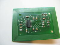
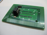
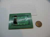
It is a device in RFID technology – card reader with integrated antenna on a PCB. The main element of the system is microcontroller Attiny13A and transceiver EM4095. The processor was closed in DIP housing so you do not need any adapter for SMD programming. The system is not a typical construction because almost all other designs are based on large processors such as Atmega8, Atmega32, PIC16Fxx etc.
The reader reads the cards in UNIQUE standard on the frequency of 125kHz. Cards are encoded by 64-bit unique serial number. The antenna has a range of about 8cm with Unique card. There is a 3x header strip – respectively: Tx (transmitting data in standard TTL, GND, VCC (5V, also 3,3V was checked and it works, but the range is smaller).
The PCB is also equipped with a LED indicating reading the card and a standard application of EM4095.
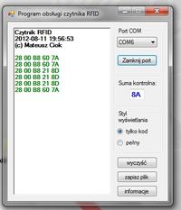
The reader sends 9 bytes of data:
- #7Eh – symbol of start of the transmission
- 1-byte of data of the card code (MSB)
- 2-byte of data of the card code
- 3-byte of data of the card code
- 4-byte of data of the card code
- 5-byte of data of the card code
- #5Eh – symbol of checksum transmission
- Checksum – XOR checksum
- #7Ch – symbol of the end of transmission
When the card is kept in the field of the reader, such a frame is sent every 700ms. The reader confirms reading the card by LED light for 350ms.
Due to the lack of hardware USART interface in the microcontroller, you have to use a software UART implementation.
Program cycle consists of initial reading the card number, decoding (Manchester encoding) and checking the parity. That prevents sending incorrectly received code to the receiving machine.
Program was written in C (AvrStudio 4 + WinAVR-20100110) and in Assembler. It takes 788 bytes.
Link to original thread (useful attachment) - Czytnik RFID 125kHz ze zintegrowaną anteną, Attiny13A