I14R10
Full Member level 3

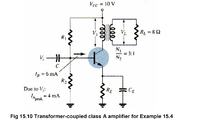
I need some help with the calculations for common source MOSFET amplifier. I want to design RF preamplifier for 50W RF amplifier. I decided to go with MOSFET. I came across this schematics

It's for BJTs, but I tried to replace BJT with MOSFET. With IRF510 https://www.futurlec.com/Transistors/IRF510.shtml
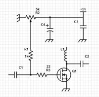
To keep it simple I removed source resistor and capacitor. So we just have that transformer in the drain.
I will first write what I calculated and then ask the questions.
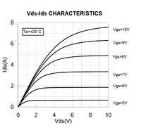
R=Vdd/Id=30/4=7.5 ohm. That is maximum resistance that should appear on transformer to allow Id=4A. I chose Id=4A because the transconductance curve was the most linear around 4A
. Instead of using R(load)=8ohm, I am using 50 ohms. That means that turn ratio should be 1:2.6 (drain : load). Now I have a load of 7.5 ohms across transformer primary coil.

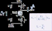
Next I calculated R1 and R2 to set up gate bias. R1=225k, R2=50k. That gives Vgs around 6.6V. And If you look at the datasheet that is the voltage needed to give Id=4A with Vdd=30V.
Does this calculations make sense?
--------------------------------------------------------------------------------------
Now if we put back source resistor, here is what I am doing
I said earlier that maximum Rd should be 7.5 ohms. Now that we have source resistor, we should take for example, Rd=6.5 and Rs=1 ohm.
Rd=6.5ohm
Rs=1ohm
Id=4A
---------------------
For no signal, the primary transformer coil on the drain is short circuit, Rd=0ohm.
But if there is a signal then Rd=6.5ohm (with 50 ohm load on secondary coil)
Vd=Id*Rd=26V
Vs=4V
--------------------
Vds=22V
We have to adjust gate bias to be 10.6V so that Vgs=6.6V
From datasheet, the transconductance is 2S. That would get gain of 13 for amplifier with source resistor and gain of 14 without source resistor.
Can somebody confirm these calculations and my comments?

It's for BJTs, but I tried to replace BJT with MOSFET. With IRF510 https://www.futurlec.com/Transistors/IRF510.shtml
To keep it simple I removed source resistor and capacitor. So we just have that transformer in the drain.
I will first write what I calculated and then ask the questions.
R=Vdd/Id=30/4=7.5 ohm. That is maximum resistance that should appear on transformer to allow Id=4A. I chose Id=4A because the transconductance curve was the most linear around 4A
. Instead of using R(load)=8ohm, I am using 50 ohms. That means that turn ratio should be 1:2.6 (drain : load). Now I have a load of 7.5 ohms across transformer primary coil.

Next I calculated R1 and R2 to set up gate bias. R1=225k, R2=50k. That gives Vgs around 6.6V. And If you look at the datasheet that is the voltage needed to give Id=4A with Vdd=30V.
Does this calculations make sense?
--------------------------------------------------------------------------------------
Now if we put back source resistor, here is what I am doing
I said earlier that maximum Rd should be 7.5 ohms. Now that we have source resistor, we should take for example, Rd=6.5 and Rs=1 ohm.
Rd=6.5ohm
Rs=1ohm
Id=4A
---------------------
For no signal, the primary transformer coil on the drain is short circuit, Rd=0ohm.
But if there is a signal then Rd=6.5ohm (with 50 ohm load on secondary coil)
Vd=Id*Rd=26V
Vs=4V
--------------------
Vds=22V
We have to adjust gate bias to be 10.6V so that Vgs=6.6V
From datasheet, the transconductance is 2S. That would get gain of 13 for amplifier with source resistor and gain of 14 without source resistor.
Can somebody confirm these calculations and my comments?


