robismyname
Full Member level 6

- Joined
- Jan 17, 2008
- Messages
- 390
- Helped
- 11
- Reputation
- 22
- Reaction score
- 9
- Trophy points
- 1,298
- Location
- Central Florida
- Activity points
- 4,603
I need some help on designing a RF choke.
A have a PCB that is supplied with 9-32 Volts where it gets regulated to 15 Volt. The pcb has a homemade-non manufacturing rf choke and some other signal conditioning components just prior to the 15 V DC/DC converter. The DC/DC converter couldn't fit in the screenshot but its just right of the 10K resistor R137 its a VHB200W-Q24-S15
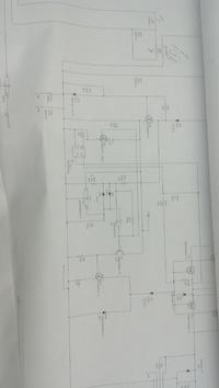
I want to design a better, RF choke but am lacking some fundamental.
My most fundamental questions are:
a capacitors passes DC, blocks RF, by way of Xc = 1/2pif Xc
a inductor passes RF, blocks DC, by way of XL = 2pifXL
a common mode choke aka an inductor made of wire blocks RF the same way as a capacitor?
1) How is it that a common mode choke which looks like an inductor behaves like a capacitor? Obviously I must have something screwed up here?
2) How do you determine if a common mode choke is needed to block RF and not capacitors and vice versa. What is the design method?
3) Since a RF choke is nothing more than a low pass filter how do i determine/select/design for a good cutoff frequency? I guess Im asking what is my cutoff frequency or rather how would I determine what my cutoff frequency should be? I cant select a common mode choke before I know what frequency I want to start to suppress. I mean there comes a point where you would like to attenuate the higher frequencies, how is this cutoff point determined? Is it based on some sort of EMC related compliance standard for the industry your electronics are working in?
4) Also are there any limits/restrictions to how low (in frequency) that you can design the cutoff frequency?
