MobiNaz
Full Member level 3
Hello all,
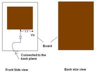
I guess someone might be able to help me. The thing is I am presently working on a 38.5 GHz RF detector. The detector has a patch antenna (gnd at the bottom) on a Roger substrate to which is attached a schottky diode which is then grounded at the cathode. The anode of the diode is connected to a RF choke (13nH).
Now this detector is radiated and should provide an output voltage equivalent to the incident power at the choke. I tested this approach at 5.3 GHz and was able to measure the output voltage by using a multimeter connected between the choke and ground of the detector (back plane). But am not getting the results (as per my simulations) at 38.5GHz using the similar approach. However , if I connect one end of the multimeter to the choke and other to the ground of the power supply, I am getting results comparable to simulations. This makes me think that it might be that the RF ground (back plane) is not a good DC ground or vice a versa.
Now , my question is how do I ensure that the back plane provides a good DC and RF grounding? and make the detector work without the power supply.

Thanks in advance.
I guess someone might be able to help me. The thing is I am presently working on a 38.5 GHz RF detector. The detector has a patch antenna (gnd at the bottom) on a Roger substrate to which is attached a schottky diode which is then grounded at the cathode. The anode of the diode is connected to a RF choke (13nH).
Now this detector is radiated and should provide an output voltage equivalent to the incident power at the choke. I tested this approach at 5.3 GHz and was able to measure the output voltage by using a multimeter connected between the choke and ground of the detector (back plane). But am not getting the results (as per my simulations) at 38.5GHz using the similar approach. However , if I connect one end of the multimeter to the choke and other to the ground of the power supply, I am getting results comparable to simulations. This makes me think that it might be that the RF ground (back plane) is not a good DC ground or vice a versa.
Now , my question is how do I ensure that the back plane provides a good DC and RF grounding? and make the detector work without the power supply.

Thanks in advance.
