frankqt
Member level 4

- Joined
- Jan 22, 2012
- Messages
- 72
- Helped
- 0
- Reputation
- 0
- Reaction score
- 0
- Trophy points
- 1,286
- Activity points
- 1,929
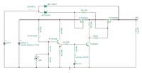
I have designed this circuit for controlling a battery operated system.
System can be turned on/off using a button (a touch button, not a mechanical on/off). Turn on is done using button and off is done using microcontroller. During on a button press would generate an interrupt for the controller and that is how controller tuns it off. (VM1, debounce in software)
The design objectives were to make it as easy and low voltage drop as possible. I like to run the battery down to 3.9V, maximum battery voltage is 6V. When USB is present power should switch to USB regardless of battery voltage.
I am a newbie to the Analog/Power Design and appreciate feedback.
The circuit below.

p.s. Switches are in there to simulate the events, button press, usb plug in and out, micro controller turn on or off etc. I can also provide a TINA simulation file if parties are interested.
Thanks
System can be turned on/off using a button (a touch button, not a mechanical on/off). Turn on is done using button and off is done using microcontroller. During on a button press would generate an interrupt for the controller and that is how controller tuns it off. (VM1, debounce in software)
The design objectives were to make it as easy and low voltage drop as possible. I like to run the battery down to 3.9V, maximum battery voltage is 6V. When USB is present power should switch to USB regardless of battery voltage.
I am a newbie to the Analog/Power Design and appreciate feedback.
The circuit below.

p.s. Switches are in there to simulate the events, button press, usb plug in and out, micro controller turn on or off etc. I can also provide a TINA simulation file if parties are interested.
Thanks
