biker.josh07
Newbie level 6

Hello
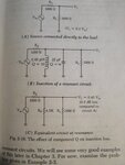
I am reading RF Circuit Design by Chris Bowick.I am a little mystified by one of the provided examples within the resonant circuit section of the book. The images provide a description of the problem.I am wondering how the effective shunt resistance is calculated to be 4500 Ohms.


First I calculated the resonant radian frequency ω to be (close approximation)
ω=1/√(LC)=1/√(0.05x10^(-6)H x 25x10^(-12)F) = 894.4x10^6 rad/s
The series resistance of the inductor is then calculated to be
R(s)=X(s)/Q= ωL/Q = [894.4x10^6 rad/s x 0.05x10^(-6)H]/10
= 4.472 Ohms
Then using the formula for calculating the equivalent parallel resistance for a series resistance and reactance.
R(p)=R(s)[1+Q^2]=4.472[1+10^2]=4.472x101=451.7 Ohms
So I am an order of magnitude from the given value in the book.Is there a mistake in the book?If not then please le me know where I went wrong.
Thanks
I am reading RF Circuit Design by Chris Bowick.I am a little mystified by one of the provided examples within the resonant circuit section of the book. The images provide a description of the problem.I am wondering how the effective shunt resistance is calculated to be 4500 Ohms.


First I calculated the resonant radian frequency ω to be (close approximation)
ω=1/√(LC)=1/√(0.05x10^(-6)H x 25x10^(-12)F) = 894.4x10^6 rad/s
The series resistance of the inductor is then calculated to be
R(s)=X(s)/Q= ωL/Q = [894.4x10^6 rad/s x 0.05x10^(-6)H]/10
= 4.472 Ohms
Then using the formula for calculating the equivalent parallel resistance for a series resistance and reactance.
R(p)=R(s)[1+Q^2]=4.472[1+10^2]=4.472x101=451.7 Ohms
So I am an order of magnitude from the given value in the book.Is there a mistake in the book?If not then please le me know where I went wrong.
Thanks

