Continue to Site

Welcome to EDAboard.com

Welcome to our site! EDAboard.com is an international Electronics Discussion Forum focused on EDA software, circuits, schematics, books, theory, papers, asic, pld, 8051, DSP, Network, RF, Analog Design, PCB, Service Manuals... and a whole lot more! To participate you need to register. Registration is free. Click here to register now.

Resistance to resistance converter with dual output

Status
Not open for further replies.

realspido

Newbie level 5
Newbie level 5
Joined
Apr 16, 2011
Messages
9
Helped
0
Reputation
0
Reaction score
0
Trophy points
1,281
Activity points
1,366
Hi everyone.
I'm trying to find a way to share a resistive liquid level sensor across two different circuits; obviously connecting the two circuits in parallel to the sender units won't work, so I was wondering if there's a way to design an electronic circuit that will read the resistance of the sender unit and simulate it to TWO galvanically separated outputs.

Rin = Rout1 = Rout2

I've seen resistance transmitters but they use voltage or current in the outputs - I'm after resistive outputs.

Any help would be greatly appreciated.

Regards,
Tom
 

A current mirror is able to generate an equal current in a neighboring circuit. The first circuit (your sensor circuit) is not directly affected.
 

Hi,

Any OhmMeter I know work with the same principle:
* either they introduce a known voltage and measure the according current
* either they introduce a known current and measure the according voltage

This "introducing" a signal modifies the overall resistance seen from a new Ohmmeter...thus such a setup can't be used.

The current mirror (input) also modifes the overall resistance, thus you can't use two independent current mirror circuits.
But you may build a current mirror with one input and two current outputs (which causes some errors).
But the output current does not behave like a true independent resistor. At least they surely are not galvanically isolated.
It may work for you or not. It depends on your circuit(s)

******

The only really gavanically isolated circuit I can think of:
* use a microcontroller and ADC and build an ohmmeter.
* use an EPOT with SPI interface for each output
* use digital isolators for each EPOT SPI.
* Don't forget the isolated power supply for each EPOT.

In detail it depends on your electrical requirements. You didn't give a single specification:
But for each development this usually is the first you have to decide.
* resistance range
* expected accuracy, precision and resolution
* excitation signal (voltage, current, frequency, waveform)
* isolation voltage
* power requirement/limitations
* size, cost....

Klaus
 

A purely analog solution should be feasible as well, using isolation amplifiers and analog multipliers to model the variable resistance. Rather complex, so the digital implementation suggested by KlausST is most likely preferable.

Obviously you need to define resistance range, resolution and accuracy before starting the design. Also expected frequency (if AC utilized) and amplitude of the excitation signal.
 

Thanks guys for the suggestions. Apologies for providing very scarce description of the application.
Basically, what I'm trying to do is to use the vehicle's OEM fuel sender and share the readings between the original fuel gauge in the instrument cluster and newly added systems monitor, details of which can be found here: https://www.simarine.net/product/st107-tank-module/
In terms of specs:
- the resistance range of the sender is 10ohm to 10kohm,
- resolution - preferably analog, but I'd be happy with 8-bit (256 positions) - although the simarine module seems to be using 16-bit microcontroller.
- excitation signal - not too sure, one circuit is the vehicle's electronic fuel gauge, the second circuit is the analog input of a microcontroller, so I imagine it would be sensing current?
- isolation voltage: simarine operates on 5V, not sure about internal voltage of the car's ECU, but will obviously be under 12V.

I'm looking for simplest solution that will do the job, I was thinking of something as simple as an electronic relay switching between the two circuits at certain frequency, but I imagine it would interfere with the sampling rate and averaging algorithm, hence scewing the results?

Look forward to hearing more thoughts.
Thanks in advance.
Tom

- - - Updated - - -

- the resistance range of the sender is 10ohm to 10kohm,

EDIT: the range of the fuel sender is actually few hundred ohms - not sure exactly how much.

Cheers.
 

I doubt that a resistance monitor with 65 kOhm range can measure a few 100 ohms with sufficient resolution, but the user manual is rather vague about the actual the resistance transfer characteristic.


A "few hundred ohms" sounds lime standard electromechanical fuel gauge. A possible simplification could be to rely on the constant excitation by the vehicle instrumentation and simply measure the gauge voltage drop. Isolation may be unnecessary if the additional circuit shares the car battery ground.

FvM, it seems that the Simarine module is 16-bit, so the accuracy would be 1ohm for that range. When you go through calibrating process the measured resistance is shown in ohm without decimal point, so that makes sense.

In regards to simplification you suggested, I'm not 100% sure whether the fuel gauges on the instrument cluster in the new-ish vehicles (2008) is electromechanical or do they use some sort of PWM controlled gauge? Either way, I'd like to avoid reading the voltage across the gauge as my Simarine module is located near the fuel sender and it also reads the level in my water tank and I'd like to keep the length of wires to the sender units as short as possible to avoid interference.
 

No problem to sense the voltage near the sender.

Where do you see 16-Bit ADC specification? It's nowhere mentioned in the manual or specs. You have been previously writing about "16-bit microcontroller" which has nothing to do with ADC resolution.

I'm under the impression that designing a resistance measurement isolator is beyond your skills. You can either revert to a more simple solution or give the project up.
 

FvM, I'm guessing it's 16-bit based on 65kohm range and the measurement resolution of 1ohm which I tested it with the pot connected to the input.

You're right, I do need help designing the circuit, which is what I was hoping to achieve here on this forum. I do have basic knowledge in electronics, but designing a circuit from scratch isn't my strong side. Having said that, I am capable of designing, manufacturing and assembling the PCB module once I get the schematic.

Any help would be much appreciated.
 

A possible simplification could be to rely on the constant excitation by the vehicle instrumentation and simply measure the gauge voltage drop. Isolation may be unnecessary if the additional circuit shares the car battery ground.

I tried that yesterday, but unfortunately that solution won't work. The voltage drop wasn't solid; the value was changing within over 30% of the maximum reading despite vehicle being stationary and the voltage drop was changing with engine's rpms. The gauge is definitely electronic (not electromechanical), so measuring the voltage drop on the gauge itself is not an option either (I believe it uses a stepper motor or PWM servo).
 

Hi,

and the voltage drop was changing with engine's rpms.
It could be:
* that the RPM causes noise. In this case a low pass filter could help.
* that the supply voltage depends on RPM. In this case a ratiometric measurement (with the supply voltage as reference) could help.

LPF: I always recommend an LPF according Nyquist. For the measurement signal and the reference signal.
In case of ratiometric measurement both filter characteristics should be equal.

Klaus
 

Klaus, I was actually wondering whether I could use the ratiometric measurement myself using the voltage from the vehicle's circuit.

If I introduced a small resistance (call it R1) - say 1 ohm, connected in series with the circuit and measured the ratio of voltage drop on R1 and voltage drop on my sender resistor (call it Rx):
20180822_150310-picsay.jpg
The result would not be sensitive to voltage changes because if voltage U changes, then voltage drop U(R1) will have changed proportionally.
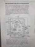
From what I gathered I could achieve the analog division using AD538 chip:
20180822_150153-picsay.jpg

where:
Vy connected to 10V ref voltage
Vz = Ux
Vx = U(R1) = U-Ux

Because it's based on op-amps, the bias shouldn't be noticeable on the vehicle's gauge, so problem of galvanic isolation goes away.

Does my idea has a chance to work?

Any thoughts would be much appreciated.
Cheers!
 

Status
Not open for further replies.

Part and Inventory Search

Welcome to EDABoard.com

Sponsor

Back
Top