Continue to Site

Welcome to EDAboard.com

Welcome to our site! EDAboard.com is an international Electronics Discussion Forum focused on EDA software, circuits, schematics, books, theory, papers, asic, pld, 8051, DSP, Network, RF, Analog Design, PCB, Service Manuals... and a whole lot more! To participate you need to register. Registration is free. Click here to register now.

Replacing the flashtube to LED in camera flash

Status
Not open for further replies.

AYahoo

Newbie level 3
Newbie level 3
Joined
Dec 8, 2008
Messages
3
Helped
0
Reputation
0
Reaction score
0
Trophy points
1,281
Activity points
1,307
Hi All, It has been long time since I used my electronic knowledge and I'm a little bit rusted :)

I have a simple camera flash circuit (similar to this):
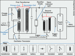
camera-flash-diagram.gif

I have 330v 102uf capacitor as the main capacitor, and the signal measured across the capacitor is:
102FullTTL.jpg

As you can see in the picture there are two pulses, one short one (highlighted in green color) and the second one that follows it immediately, and then the charge.
the volatge goes from 330v to 280v on the first pulse and then from 280v to 50v (roughly), I need to preserve the duration of the pulses, but change the "lamp" from flashtube to LED (I know the intensity is different, I don't need the intensity). As I know the LED will work on 3v so I need to change the voltage of the output, I thought All I need to do is replace the flashtube with a resistor & a led in series and the led will work, but I'm not sure if I'm correct and if the "timing" of the pulses will still be the same.

Also what resistor should I use? and what should I do with the trigger plate? (that is connected to the flashtube).

Thanks in advance!
AYahoo
 

Why do you want to preserve the pulse waveform, the first little step is the trigger electrode taking a little current to ignite the tube before the tube conducts and discharges the capacitor completely.
Frank

Thanks for the replay, but you are wrong, the first pulse is a preflash used to measure the needed amount of flash (called TTL).
I need to preserve it, I just don't know how :)

Thanks,
AYahoo
 

I think you really need to start over again. The 1.5V is too low to operate a white LED so you still need something to increase the voltage but going to over 300V isn't the way to do it. The increased voltage at present comes from the first transformer, the second one is just to produce the trigger voltage to the tube. So the TTL metering flash and the photo flash are both generated by closing the trigger switch.

I would suggest a simple low voltage inverter, something like the "Joule thief" and wire the trigger switch in series with the LED. Google for "Joule thief" and you will get lots of suitable designs.

Brian.

Hi Brian, Thanks for the info, BUT, maybe I wasn't clear, I have this circuit, this is a camera that I own, I can't "start over" since this is a built in circuit in the camera, I need to change the flashtube and attach what ever components that i can to it.

Thanks,
AYahoo
 

I will never work. The difference between a flash (Xenon) tube and LED is that the tube will not conduct until maybe 600 - 700 volts is applied directly across it. An LED in comparison will conduct at only 3 - 4 volts. The tube is run at a lower voltage, typically 300V and will not flash until a high voltage pulse is applied at the trigger electrode. This does two things, being closer to the common end of the tube it has a much shorter distance (= needs lower voltage) to ionize through and it when ionized the cascade effect is to allow the remainder of the tube to conduct. When the voltage across it has fallen enough, the tube extinguishes and the inverter starts to recharge the reservoir for the next flash. The second transformer, used to generate the trigger is usually just a tapped inductor, used as an auto-transformer.

To make an LED work, you need to wire it in series with the trigger switch but ensure a lower voltage is always present to power it. Unfortunately, the available 1.5V is not enough so you still need some kind of inverter to give it a boost. You need to change high voltage/low current into low voltage/high current. The existing trigger electrode and transformer become redundant, the last thing you want connected to an LED is a spike of several hundred volts!

Brian.
 

Status
Not open for further replies.

Part and Inventory Search

Welcome to EDABoard.com

Sponsor

Back
Top