Continue to Site

Welcome to EDAboard.com

Welcome to our site! EDAboard.com is an international Electronics Discussion Forum focused on EDA software, circuits, schematics, books, theory, papers, asic, pld, 8051, DSP, Network, RF, Analog Design, PCB, Service Manuals... and a whole lot more! To participate you need to register. Registration is free. Click here to register now.

Remove glitches in output frequency of ring oscillator

Status
Not open for further replies.

antlhem

Member level 1
Member level 1
Joined
Dec 8, 2016
Messages
41
Helped
0
Reputation
0
Reaction score
0
Trophy points
6
Activity points
364
I am making tests with a ring oscillator (RO) in ADEL Cadence. But when I increase the size of the RO from 13 to 121 stages there are glitches in the output signal of the RO (image attached). How can I make the output frequency of the RO a stable signal? Because this is also generating errors for aging simulation in ADEL. Glitches in output frequency of the RO - 21 Jan 2020.PNG
 

I am making tests with a ring oscillator (RO) in ADEL Cadence. But when I increase the size of the RO from 13 to 121 stages there are glitches in the output signal of the RO (image attached). How can I make the output frequency of the RO a stable signal? Because this is also generating errors for aging simulation in ADEL. View attachment 157428

Those aren't "glitches". They are full scale, fully settled reswitch
(chatter). Moreover it appears repetitive.

Your RO should have one and only one cycle of a standing wave.
Stop the cycle and see whether you have sub-cycles within the
bit field. Like do you have

11111100000...0001111111111

or

11111101000...0001011111111

The latter problem maybe wants a better initialization or logic
that scrubs rogue singlet bits continuously.

It may be that, if you are current starving this RO trying to get
low frequency, you are forcing the stages to operate with so
little gain that there is a lot of local noise pickup, and (say)
the next stage's output switch bounces the predecessor's
input to reswitch it. Look at the input amplitudes, are they
well formed "digital" (as a non-starved RO would be, at that
stage count) or are they low amplitude centered around the
switchpoint, thus near zero noise margin?

Of course in an ideal simulation many coupling modes are absent.
Add interconnect C, or RLC, and you'll see some icky stuff I bet.

Consider getting your low frequency by fewer stages and
a post-divider (like your successful 13, and a /8 or /16 prescaler?)
 

i take it 13 stages works as you want it to,
but 121 stages does not

where does it break down? 21 stages? 37 stages? 93 stages?
is the propagation delay the same in all stages?

look up ring oscillator jitter

https://en.wikipedia.org/wiki/Ring_oscillator

what frequency are you looking for?
 

@dick_freebird, thanks for your reply. The signal as it shown in the screen shot remains the same, no sub-cycles. But is different for each aging time. What could be a better initialization or logic? So far, I am using a Vpulse to activate the RO, and I am also using capacitors. I am attaching a screen shot of my 13-RO, the 121-RO is build in the same way but with 121 inverters. What is the configuration that you suggest when you say RCL? Could you add a diagram for this?
This is my schematic 13ro.jpeg


@wwfeldman, thanks for replying. I jumped straight to 121 because I am looking to test 121 and 151 stages, the output frequency doesn't really matter to me as long as it is stable. This is my schematic for 13 but is basically the same for 121.
 

Attachments

  • 13ro.jpeg
    13ro.jpeg
    95.7 KB · Views: 199
  • 13ro.jpeg
    13ro.jpeg
    95.7 KB · Views: 197

It's usually expected that a RO oscillates at the lowest possible frequency with a period equal to twice the gate chain delay, without a frequency selective circuit.

I'm not sure if the assumption is always true, but there may be specific issues that only occur in a simulation.
 

since the time scale on the simulation in your first post is in ns, and based on
dick_freebird's comment that the signal appears repetitive, it looks like you have a
period of 50 ns for a frequency of 20 MHz

there are better and more stable (time and temperature) ways to produce 20 MHz

what frequency are you looking for?

Thanks for your comments. Look I am testing a library, so is not really about a target frequency, instead is about a proper test on the inverters that I have in the library and specially using RO. Do you know a way to make this ring configuration stable?
 

Thanks for your comments. Look I am testing a library, so is not really about a target frequency, instead is about a proper test on the inverters that I have in the library and specially using RO. Do you know a way to make this ring configuration stable?

since it is a test of the model of the inverter, you might want to test it the way a
semiconductor manufacturer tests the real thing, as the goal (i assume) is to match
the real thing as close as possible.

Since ring oscillators appear to be well known to have these issues, maybe this indicates
the inverter model in your simulatoer is working correctly?

regarding ring oscillator jitter:
google ring oscillator jitter

look for items:

Jitter in ring oscillator UCSB ECE

jitter in ring oscillators - WPI

there are several more

this talks about a physical implementation
http://forums.xilinx.com/t5/Impleme...500-1000PPM-is-this-typical-value/td-p/928060
 

google ring oscillator jitter
What we see in post #1 is not jitter. It's an unstable oscillation mode.

Apart from the question it's a real hardware effect or a simulation artefact, what's the purpose of increasing the number of gates? To characterize the gate, it should be sufficient to achieve stable oscillation with a shorter inverter chain.
 

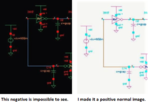
Color-on-black is the Cadence default and simple screen
shot is what you see. When I do "paper" documentation
I always turn them to black-on-white, but that's another
4 clicks per pic.
 

Status
Not open for further replies.

Part and Inventory Search

Welcome to EDABoard.com

Sponsor

Back
Top