Continue to Site

Welcome to EDAboard.com

Welcome to our site! EDAboard.com is an international Electronics Discussion Forum focused on EDA software, circuits, schematics, books, theory, papers, asic, pld, 8051, DSP, Network, RF, Analog Design, PCB, Service Manuals... and a whole lot more! To participate you need to register. Registration is free. Click here to register now.

Relay Coil Theory Class

Status
Not open for further replies.

msenkpiel

Newbie level 4
Newbie level 4
Joined
Jul 17, 2015
Messages
6
Helped
0
Reputation
0
Reaction score
0
Trophy points
1
Activity points
63


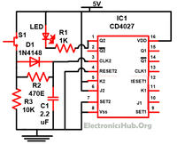
I am using the above schematic for a JK Flip Flop circuit. It works fine with the LED, but I need it to actuate a relay. When I try to replace the LED with a relay, it doesn't energize the coil. If I energize the coil with 5v from the power supply, it energizes, but 5v at pin1 of the IC doesn't.

From posts here, I have gathered that I probably need a transistor to get the right current for the relay coil, but I would like to understand the theory of why it works with the LED, but not the relay, what the transistor does to fix this, etc.

I am trying to use this 5v relay that has a coil resistance of 122 ohms:https://www.amazon.com/gp/product/B008MPKBZY?psc=1&redirect=true&ref_=oh_aui_detailpage_o01_s01

Thanks for the help!
 

Hi,

5V and 122 Ohms means 40mA.

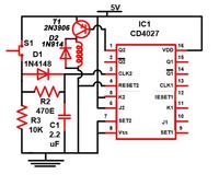
Find a PNP transistor with about >=100mA current rating and >=20 V voltage rating.
And use a diode with about the same ratings.

Use the relay and connect the diode across the coil. Cathode to + of coil, anode to - of coil.
Connect - of relay coil additionally to gnd of your circuit.
Disconnect the LED.
Connect the transistor emitter to +5V of your circuit.
Connect base to the resistor (where the LED was)
Connect the collector to the relay +.

Good luck

Klaus
 
an LED requires less current than a relay in ON state.

LED current can be supplied by the IC(CD 4027).
But it cannot supply the current required for the rely.

In your case , the relay (5v,122ohms) you have chosen , requires a current of approx. 45mA .
This cannot be spupplied(or sourced ) by the IC.
So, you use a transistor to meet the current requirement.

( Even though you said that LED is switched ON by the IC itself , you might have observed that the brightness may not be like a normal LED)
 

Simple
LED required very low current to glow. But relay require more current.
For your relay 40mA current require to drive (5V/122Ω = 40mA). Your TTL IC pins(1) do not have this much current source/sink capacity. If you use a transistor, the current will flow through the transistor (From power supply +Ve - relay – Collector –Emitter – Power supply -Ve).
You can switch on this transistor by TTL IC.
 

LED required very low current to glow.
No it does not! The LED uses as much current as it is fed. But its current is limited by the 1k resistor in series with it. If the LED is a 2V red one then the 1k resistor has 5V - 2V= 3V across it then Ohm's Law calculates the current to be 3V/1k= 3mA. The Cmos IC with a supply that is only 5V has an output current of only a few mA.

But relay require more current.
Yes, MUCH more current.

Your TTL IC.... You can switch on this transistor by TTL IC.
No. It is a Cmos IC, not a TTL IC. The Cmos IC can switch on a transistor.


I modified the circuit according Klaus' suggestions (except I removed the resistor as I think it was there for the LED). I'll try this when I get home. Thanks for the help!

PS - What is the purpose of the diode across the coil?
 

So when it de-energises the back emf path followed is round the diode and back into the coil and not into the CD4027 pin.

(I'm doing a similar circuit, and whilst trying to get it to work this afternoon was reminded that using a MOSFET, ZVN4206 in my case - the manufacturer has an app note specifying this use: relay driver - eliminates need for diode around relay and several resistors).

Glad your circuit is working.
 

Do not switch on!
Put the resistor back in again!

Reason: when pin 1 is low, it tries to put full 5V across the base-emitter junction of the transistor. There is a good chace either the transistor, the IC or both will be damaged. The resistor will limit the base current to a safe level. You can probably increase the value to 1K to save some current and still operate the relay properly.

Brian.
 

For people who did not know about the high voltage developed when an inductor has current then the current is suddenly stopped:
1) Hold the relay terminals in ONE hand (do not use both hands because you do not want to zap your heart).
2) Power the relay with a battery.
3) Disconnect the battery and feel the high voltage in your hand.

The diode conducts and clamps the generated voltage to 0.7V more than the supply voltage.
Without the diode then the transistor gets zapped when it turns off is destroyed.
 

K, I put the 1k resistor back in. It works great!

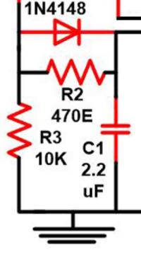
Except that I am having trouble with the "filter" section (not sure if this is the right term). The switching is not 100% reliable and seems to be dependent on the switch used. It's imperative that the circuit flip flops reliably with each press of the button. I've monkeyed with the cap values, but since I don't completely grasp the theory behind this section, I'm kinda floundering...

Thanks everybody!


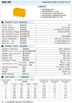
I found the data sheet for this relay. I have never seen a relay data sheet with four different 5 volt winding's listed.
 

Attachments

  • hk19f_01.jpg
    hk19f_01.jpg
    140.1 KB · Views: 87

Hi,

Connect the coil - as close as possible to the battery/power supply with an extra wire, to stop the influence of relay switching.

Klaus
 

Here is the debounce circuit you mean by filter, you'll know if the 4027 is active high or active low, I haven't looked at the datasheet.

You need to play with RC values to suit your needs, I pretty much always use 10nF and 1M on pushbutton line - that gives a minute (not time, but quantity) yet noticable gap before you can re-press the button, because I found lower cap value made it less reliable, and higher cap value means you wait "a long time" ie millisecond-length to be able to press button again - which becomes an irritating delay for a user..., and 100K to +V (or -V, depending), but 10K is as good.

pushbutton debounce schematic.JPG


This is the latching circuit I have come up with to open and close a flow valve for my shower. The valve motor has limit switches to stop the motor when the valve is fully opened or closed. There is a pushbutton inside and outside the shower with LED indicators. The debounce circuit is working pretty good (thx d123!), but now I have an issue with false triggering.

When this circuit is on the bench using my variable dc power supply, it is not affected, but when I use a 5V wall wart and hook the circuit into the system, it can trigger apparently randomly. I can tell you, it is a freaky thing to have a shower start in the middle of the night when you are by yourself...

Anyway, I suspect this has something to do with a power fluctuation, e.g. when the HVAC or fridge turn on or off, but don't know how to isolate my circuit from these outside influences. Any ideas? Thanks!
 

Hi,

From what you say, good decoupling from the dodgy sounding wall wart might be the answer.

Not sure if any point tying Q output to ground, as it's an output, not an input so should be completely irrelevant.

Don't know enough about relays to say if putting 24VAC and 5VDC on same side is not a good idea. If can spare the voltage, looks like it if only a 2N3906 there, the indicator LEDs + their respective ~470R resistors could be paralleled on the Q' output with the transistor, and in that way not mix AC and DC so close on a relay.

Things to try could be, if not already done so:

Bypass 4027 supply pins with 1 to 10uF, or 0.1 and 1uF in parallel could work well.

Maybe a 1K resistor between J and K to V+ and another 1K from Reset and Set to ground, and "place" V- along with V+ behind above-mentioned bypass capacitors.

Is the 5V wall wart trustworthy? :) Rather than sit for hours watching if its ouput fluctuates much with a voltmeter, if it's one of those 5 - 12V types and you have any spare 5V regulators, put one between the DC adapter and your circuit. And either way, certainly do decouple/bypass the wall wart connections into the circuit with anything from 10 to 100uF; could try 0.1uF, 1uF, 10uF and 100uF in parallel - maybe overkill but it covers a range of high-ish to low frequencies and could be enough reservoir cap to stop fluctuations that cause false triggering.

By the by, or bye the bye, never remember, I saw a solenoid driven flow valve a few days ago, available as 1 inch or smaller diameters.

I'd start with simplest things like bypassing circuit input and the 4027 supply pins, the 1K resistors, and if that made no difference I'd consider exorcising the bathroom ;) - birds or something like rodents move around inside my roof sometimes at night - it's creepy when you're half-asleep, so I empathise.
 

Status
Not open for further replies.

Part and Inventory Search

Welcome to EDABoard.com

Sponsor

Back
Top