Continue to Site

Welcome to EDAboard.com

Welcome to our site! EDAboard.com is an international Electronics Discussion Forum focused on EDA software, circuits, schematics, books, theory, papers, asic, pld, 8051, DSP, Network, RF, Analog Design, PCB, Service Manuals... and a whole lot more! To participate you need to register. Registration is free. Click here to register now.

Relative phase compensation technique

Maitry07

Full Member level 2
Full Member level 2
Joined
Jun 29, 2022
Messages
136
Helped
0
Reputation
0
Reaction score
0
Trophy points
16
Activity points
1,237
Hello support team,

I am working on a high speed ADC + FPGA . High speed ADC is multi channel that can take CW tone RF input and convert it into decimated I,Q digital data through DDC technique. I am providing 40 MHz RF input to high speed ADC channel 1 and channel 2 with the same cable length through function generator. My FG's channel 1 phase is 9.058 deg while My FG's channel 2 phase is 0 deg. FYI: I have checked my input's phase difference in MSO and validate that it is 9.058 deg

My FPGA is capturing decimated digital I,Q data for both the channels simultanously and I am using CORDIC IP core to convert the I,Q to absolute phase for both channel 1 and channel 2.
now, I am using subtractor IP core to have a difference between absolute phase 1- absolute phase 2 to generate relative phase.

and when I am checking output of relative phase , it is approximately 15 deg instead of 9.058 deg. weather this variation is due to slight mismatch between both the front end channel of my high speed ADC?
FYI: I am using AFE7900 High speed ADC.

What need to be done in order to compensate this relative phase misatch? is it ok to subtract 6 deg from the final relative phase output or any other proven method you can suggest to compensate this relative phase mismatch?

Awaited your response. if you need any other details, do let me know.
 
For any problem either avoid it at source or let it in and then compensate it. Choose whichever is cheaper, easier...
 
Actually I am using a standard source and my high speed ADC is also custom PCB in which I have taken care to have minimal mismatch between the RF front end chain. still I am observing this. So Anyhow I need to compensate this in digital signal processing only. so which method is better and suitable for this kind of compensation for relative phase?
 
Actually I am using a standard source and my high speed ADC is also custom PCB in which I have taken care to have minimal mismatch between the RF front end chain. still I am observing this. So Anyhow I need to compensate this in digital signal processing only. so which method is better and suitable for this kind of compensation for relative phase?
In that case you can readily delay one channel that is in advance of other channel by using a pipe of registers. each register will give delay of one sample period. You will need to find out how many samples match your delay of degrees. If delay difference stays fractional of a sample then you got more work to do.
 
Hello,

Can you elaborate more on the above. actually this is my assumption, that it may be possible due to slight mismatch. but how can I verify this.

My High speed ADC front end channel are all identical. same transmission line length and same lumped components. I am using same length cable in function generator. Function generator after cable is showing me 9 deg difference between channel1 and channel2.

I,Q data are captured through FPGA via JESD interfacing and processed via CORDIC IP core to generate absolute phase. after that I am simply using subtractor and one more logic to convert -pi to pi format to 0 to 2*pi .

In this why I am getting this phase meausrement as 15 deg instead of 9 deg?
and how can I figure out what is generating this delay? I have re initiated this question as I do not understand the above answer . could you please elaborate more?
 
I thought you wanted to compensate rather than find out the source of problem!! Anyway that is too much processing to identify the cause. If it is me I will capture both channels instead of measuring phase difference. Provided you trigger both channels at same instant then you can directly see phase difference if any.
 
actually, My plan is to have accurate relative phase measurement. if it is possible without figure out the source of problem, then also it works for me.
My function generator is having align phase option so actually I am triggering that phase align option already . after that I have interface external BNC TEE on both the channel of function generator. one output of each BNC TEE is going to MSO direct and other output of each BNC TEE is going as an input to high speed ADC. so I am seeing 9 deg via direct relative phase difference reference with align phase option. at the same time, the digital data generated from relative phase DSP is according to 15 deg. that's why this confusion creates. so how to compensate this, that is my main aim
 
Well it is hard to know.
I can only ask: is your function generator one box only, triggered by one trigger? does it have tolerance issue? is the 9 degrees deliberate setting you chose?
Are ADCs synchronised on both channels?
 
My function generator is AFG31002. And yes it is one box only and have the phase aligned option. High speed ADC is AFE7900 and both channels are synchronized. also the JESD interfacing is also providing synchronized I,Q digital data on the same clock. no I have choose this 9 deg as random.

Also, when my RF input power level is near to full scale , I am getting accurate relative phase digital data. but as soon as I reduce my RF input power level to 10 mvpk-pk which is my lowest required power level, my relative phase output is getting inaccurate so that I am using moving averaging with the factor of 3.
I have checked it with 9 deg at near full scale power. and 271 deg at 10 mVpk-pk power. I am getting relative phase digital data in between 273 to 280 deg.

So, here I have observed 2 issues. 1) difference in reference vs measured 2) lower accuracy at 10 mvpk-pk.

what can be done to mitigate this kind of issue?
 
Hi,

I´m the guy how wants to know the reason / the root cause.

So my first "debug" idea was to give the same signal to both inputs and see what happens.
(Indeed to destinguis: is the problem before or after the ADC?)

If the cause is "after the ADC" and you see the phase shift is stable, then I see no problem to add/subtract a calibration value to the phase.

If it´s before the ADC I´d do further investigation.

Klaus
 
I'd expect the measurement setup is specified for a certain range of phase difference, frequency, magnitude. Correct operation would be verified by varying all parameters, not just apply a known phase difference with fixed frequency and magnitude.
--- Updated ---

If you experience a phase error of 6 degrees, it might be interesting where it's originated. You can also treat the measurement circuit as a black box, don't care about internal operation. But you surely want to know if the phase deviation is constant over phase difference, frequency and magnitude. Otherwise you are most likely unable to compensate it.
 
Last edited:
Hi,

I´m the guy how wants to know the reason / the root cause.

So my first "debug" idea was to give the same signal to both inputs and see what happens.
(Indeed to destinguis: is the problem before or after the ADC?)

If the cause is "after the ADC" and you see the phase shift is stable, then I see no problem to add/subtract a calibration value to the phase.

If it´s before the ADC I´d do further investigation.

Klaus
Hello,

below is the analysis and details.
1. I have use BNC TEE interfaced with Function generator's channel 1 and channel 2.
2. One ports of BNC TEE from each channel is direct interfaced with the MSO.
3. While the other ports of BNC TEE from each channel is given at the input of high speed ADC.
4. I have aligned the phase in function generator with 0 deg phase difference, 90 deg phase difference, 270 degree phase difference.
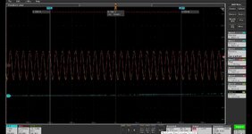
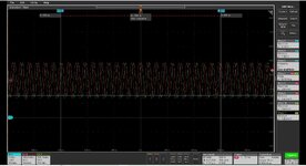
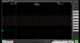
5. In the MSO, I am getting the phase difference of 2.8 deg ( this is not accurate when both the channels are having 0 deg or same deg . the phase difference in MSO for the direct reference input). while for the generation of 90 deg and 270 deg phase difference, the MSO is showing 92.5 and 273 deg approx. ) . I have attached 3 screenshots for this 0 deg, 90 deg, 270 deg phase aligned generation). that means the Function generator is providing approximate 2.5 degree offset with aligned phase as well.
6. For these 3 different cases at 40 MHz , near full scale power , My Relative phase digital output is equivalent to 5.3 to 6 deg, 95.4 to 96.1 deg and 275.8 to 276 deg stable output samples.

so, at near full power the variation remains approximately 3 deg with respect to the reference is shown in MSO.

This becomes inaccurate with input power reduce to 10 mVpk-pk.

so, Can I subtract constant offset at the output of relative phase to compensate this variation?
--- Updated ---

I'd expect the measurement setup is specified for a certain range of phase difference, frequency, magnitude. Correct operation would be verified by varying all parameters, not just apply a known phase difference with fixed frequency and magnitude.
--- Updated ---

If you experience a phase error of 6 degrees, it might be interesting where it's originated. You can also treat the measurement circuit as a black box, don't care about internal operation. But you surely want to know if the phase deviation is constant over phase difference, frequency and magnitude. Otherwise you are most likely unable to compensate it.
over phase difference it is constant. but over magnitude, the phase deviation is same but inaccurate.
 

Attachments

  • Capture.JPG
    Capture.JPG
    123 KB · Views: 6
  • Capture.JPG
    Capture.JPG
    141.7 KB · Views: 7
  • Capture.JPG
    Capture.JPG
    141.4 KB · Views: 7
in short you are injecting two tones at
frequency 40MHz
ADC sampling: unknown
decimation factor: unknown
phase as below in degrees

generator setting----oscilloscope---- your measurement
0---------------------- 2.8--------------------5.3~6
90--------------------- 92.5------------------ 95.4~96.1
270--------------------273-------------------275~276

so the generator is not doing well and your measurement is worse.
You shouldn't jump to patching errors before you know what is going on.

I suggest -as starting point- you apply same signal to both ADC ports i.e. same exact tone then you can make some conclusions about your logic.
 

LaTeX Commands Quick-Menu:

Part and Inventory Search

Welcome to EDABoard.com

Sponsor

Back
Top