Continue to Site

Welcome to EDAboard.com

Welcome to our site! EDAboard.com is an international Electronics Discussion Forum focused on EDA software, circuits, schematics, books, theory, papers, asic, pld, 8051, DSP, Network, RF, Analog Design, PCB, Service Manuals... and a whole lot more! To participate you need to register. Registration is free. Click here to register now.

Related to use of transformer of 240/12 1amp to 440v

Status
Not open for further replies.

milind.a.kulkarni

Advanced Member level 3
Joined
Oct 6, 2011
Messages
922
Helped
214
Reputation
428
Reaction score
208
Trophy points
1,333
Location
Bangalore
Activity points
7,448
How to use transformer of 240/12v 1 amp on 440v on primary using resistors , what are design consideration for selection of the resistors? Is there is any circuit that is recommended? Please guide me.
 

Use Ohm's Law. You must know your load current and from it you can derive the value of the dropping resistor.
The best way, however, is to make a transformer from 440 to 12 V. You can also use two 220 to 6 V transformers and put both their sides in series. Be aware of insulation and safety issues on 440 V side as well as 220 V.
 
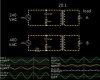
According to my simulation...
A 3200 ohm resistor will drop 440 VAC to 240 at the transformer. (Although to me it seems difficult to believe.)

One thing that helps a lot is a capacitor across the primary, for power factor correction. It greatly reduces current draw.


The transformer parameters are simulated, of course. Only real-life testing will prove whether the above schematics are realistic, and whether the 3200 ohm resistor is a feasible method.
 
Hi both of you,

First of all thanks for such a quick reply.

I went with the calculation and then realize that current in primary side is 0.05 amp for 240/12 1amp transformer and it's impedance come to be 4800 ohm at full load hence if I need to maintain the same current on primary side using 440v then total impedance of circuit comes to be 8800 ohm , thus I need to add 4000 ohm resistance in series with power capacity of 10 watts . I understand this from theory but what I am looking at is
1) is this design is reliable to work with 440v ac ?
2) any other thoughts like effect of power fluctuations will hamper the performance?
3) dose it is recommended to use capacitors across the transformer such that it will help reduction in the power rating of resistor ? If yes how to compute value and rating of capacitor.

Thanks and regards

Milind
 

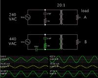
As an alternative to using a resistor to drop AC voltage...

There is also the idea of capacitive drop. This is feasible since a small amount of current (50 mA) is needed through the primary.


The capacitor values are tricky to adjust properly. If I increased one, I had to decrease the other.

I adjusted the cap values so as to obtain the smallest current draw. Small variations can make a large difference in voltage at the load.

I believe the two caps together act as a capacitive AC voltage divider.

I was not able to obtain power factor correction, meaning I could not get the supply waveforms to synchronize, as to voltage and current.
 
I suppose you have three phase to form 440V. Can you simply use one phase and neutral this will give you 220-230V?

Its not simple to use resistor or capacitor, you will have huge dissipation needs if you want full power from transformer. Easier is to use appropriate transformer for that input voltage. Some options are to use autotransformer to adjust voltage, triacs dimmer,.... but then its easier to get appropriate transformer. One additional option is to have the same one more transformer, and connect both primar coils in serie.


Best regards,
Peter
 
Hi Petar,

Many many thanks for such a prompt response...... Actually we have the 440/12 1 amp transformer but the things was it was bit bulky and costly too....as the 230/12 1 amp is compact in size and cheaper too... thus we are exploring this idea to use...I like your first view of using phase and neutral concept for 230v transformer but the problem there is in the field most of the time supply comes from delta secondary transformer i.e. 3 phase 3 wire supply.....not 3 phase four wire supply.... I think you strongly suggest not to go with resistor based voltage reduction approach because of power dissipation problem. I respect that....but just to brain storm here apart from power dissipation any other issue that you envisage in this case.

regards,

milind
 

Maybe to modify primary winding if separate and accessible or to rewind complete transformer with different primary ratio.


Best regards,
Peter

- - - Updated - - -

There is triac solution for 220V to 110V, but maybe you can adjust or use this just as some spark for new idea.

220V%20to%20110V%20schematic.gif
 
Hi peter ........ one question you mention on above circuit DB1 and DB3 .... did u mean diode bridge.... I am not able to understand why did u want to have diode bridge in series with triac gate terminal ...... circuit appears to be nice but may be costly (I am not sure ) and use lot of power components it seems....

with regards,
milind
 

One thing that helps a lot is a capacitor across the primary, for power factor correction. It greatly reduces current draw.
Apparently you assumed an unrealistic high magnetizing current in the simulation (cos phi at rated load < 0.3 !).

A point that hasn't been said yet, is the 12V/1A load expected permanently with no risk of disconnection? Otherwise the transformer would be burned in the voltage divider circuit.
 
Apparently you assumed an unrealistic high magnetizing current in the simulation (cos phi at rated load < 0.3 !).

Yes, I thought I needed to do some experimenting with the transformer parameters.

Falstad's simulator contains only a few parameters for a transformer:
primary inductance (default is 4H)
turns ratio
coupling coefficient (default is .999)
option to use trapezoidal approximation

The voltage ratio is 20:1.

Therefore the current ratio should be the inverse (1:20). The load draws 1.41 A (sine peaks) at 12 VAC. Therefore I expected the primary to draw 71 mA (peak). Maybe a little more.

Instead the primary was drawing 280 mA (peak).

I started experimenting with values. I found I had to increase the primary's inductance to 30H, to drop the current draw down below 90 mA.

This was the case for both the simple bare layout (supply > transformer > load), and the resistive drop layout. The resistive drop with a transformer is unconventional, and because of the unexpected volt levels I was uncertain how to optimize the layout.

However by installing the capacitor across the supply, I found I could stay at the smaller Henry value. It also brought the supply voltage waveform phase into sync with the ampere phase (which I believe is the aim of power factor correction). So that was preferable to using a Henry value upwards of 30 or 40 Henry's.

I have never installed a capacitor across a power transformer nor have I heard of it being necessary at these low power levels. I'm not altogether certain it is necessary in this case either. Transformer theory is complicated, and my knowledge is incomplete.
 

Apparently you assumed an unrealistic high magnetizing current in the simulation (cos phi at rated load < 0.3 !).

A point that hasn't been said yet, is the 12V/1A load expected permanently with no risk of disconnection? Otherwise the transformer would be burned in the voltage divider circuit.

Hi FvM,

Can you bit elaborate the description, actually I am planning to convert 12 volt secondary to DC and use it. Peter's suggatation is not to use voltage divider circuit for such a conversion because of huge power loss in the resistor at full load and even fair enough. My interest here is understand dose capacitor will help in reduction of power rating of resistor or not. Also any other problem like voltage surge generation because of use of transformer primary connected with capacitor parallel. If power loss in the resistor is not a point of concern how to compute the rating of capacitor.

With regards,

Milind
 

The parallel capacitor won't be necessary if the transformer has the usual low magnetizing current, at least it's not essential.

A series capacitor with a smaller resistor to limit inrush and surge currents would be my favourite solution. But it can only work if the transformer has a guaranteed constant load. In case of a DC power supply a power zener diode that can absorb the full output power if the regular load is disconnected would be mandatory for safe operation. Also the primary should be fuse protected.
 

R2 needs reacalculation, also the parallel RC circuit, if used at all.

My suggestion was a Z-diode directly after the rectifier to safely limit the voltage across the transformer. A correctly calculated R2 could achieve the same.

A series capacitor would have a considerable lower value (about 0.68 µF), but according to AC network laws, it's operating voltage is about 370 V, it must be rated for 400 V AC. The peak current limiting resistor should have a slightly higher value, e.g. 50 to 100 ohm.
 
Status
Not open for further replies.

Part and Inventory Search

Welcome to EDABoard.com

Sponsor

Back
Top