David_
Advanced Member level 2

Hello.
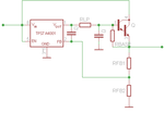
I've been working on a lab supply for some time and I had thought that I had solved how to supply the high current I wanted from a low-noise linear regulator through using a NPN power transistor at its output as this:

The low-pass filter is not in use in my prototype, the real circuit are controlled by digital means but the picture above is how my circuits looks like with some modifications to the resistor voltage divider for control of output voltage.
First I had no NPN on the output and everything worked just as thought but when I added that(along with some other modifications to the board) the output when told to go to 0V never goes below 5,5V and I thought something is wrong.
I am not experienced within electronics but what was wrong was my thought that something was wrong.
I read the datasheet to a NPN power transistor(by the way, is "Power transistor" the same as "Darlington transistor"?) and I noticed the Vbe voltage was to be 5V... But that would mean as far as I know that this circuit will never cut it for me and I need to re-think how to get my low-current output low-noise voltage regulator to supply its variable voltage while maintaining a current of 5A. I could adapt the circuit to use the PNP transistor way of boosting a regulators current but I want to ask if there are any way around my problem while still using the NPN design?
Answers I have gotten earlier in other threads on this forum has lead me to believe that its gives me benefits when using my current circuit through the fact that the transistor is within the regulators feedback-loop and as such does not degrade any characteristics, but the PNP way of doing it is does not put the transistor within any feedback-loop and my regulator can only supply 50mA above which the PNP would take over(or is it adding to the already supplied 50mA).
I have not knowledge enough to be able to measure the proposed circuit to detect if it papooses any problems.
Regards
- - - Updated - - -
A possibility would be to ditch the integrated linear regulator circuit and apt for an linear regulator made of transistors and a opamp or any such scheam.
I've been working on a lab supply for some time and I had thought that I had solved how to supply the high current I wanted from a low-noise linear regulator through using a NPN power transistor at its output as this:

The low-pass filter is not in use in my prototype, the real circuit are controlled by digital means but the picture above is how my circuits looks like with some modifications to the resistor voltage divider for control of output voltage.
First I had no NPN on the output and everything worked just as thought but when I added that(along with some other modifications to the board) the output when told to go to 0V never goes below 5,5V and I thought something is wrong.
I am not experienced within electronics but what was wrong was my thought that something was wrong.
I read the datasheet to a NPN power transistor(by the way, is "Power transistor" the same as "Darlington transistor"?) and I noticed the Vbe voltage was to be 5V... But that would mean as far as I know that this circuit will never cut it for me and I need to re-think how to get my low-current output low-noise voltage regulator to supply its variable voltage while maintaining a current of 5A. I could adapt the circuit to use the PNP transistor way of boosting a regulators current but I want to ask if there are any way around my problem while still using the NPN design?
Answers I have gotten earlier in other threads on this forum has lead me to believe that its gives me benefits when using my current circuit through the fact that the transistor is within the regulators feedback-loop and as such does not degrade any characteristics, but the PNP way of doing it is does not put the transistor within any feedback-loop and my regulator can only supply 50mA above which the PNP would take over(or is it adding to the already supplied 50mA).
I have not knowledge enough to be able to measure the proposed circuit to detect if it papooses any problems.
Regards
- - - Updated - - -
A possibility would be to ditch the integrated linear regulator circuit and apt for an linear regulator made of transistors and a opamp or any such scheam.


