Continue to Site

Welcome to EDAboard.com

Welcome to our site! EDAboard.com is an international Electronics Discussion Forum focused on EDA software, circuits, schematics, books, theory, papers, asic, pld, 8051, DSP, Network, RF, Analog Design, PCB, Service Manuals... and a whole lot more! To participate you need to register. Registration is free. Click here to register now.

Rectifier diodes with bypass cap´s & gounding speaker basket´s

Status
Not open for further replies.

mikaelmark

Junior Member level 2
Joined
Sep 21, 2019
Messages
21
Helped
0
Reputation
0
Reaction score
0
Trophy points
1
Activity points
238
By default design´s for power supply section in a pre amp, headphone amp or a DAC and when replacing standard rectifier diodes 1N400x with BYV27-200, I use to solder a 0,1 uF capacitor for each diode to eliminate unwanted high voltage peakes and noise.


But as I´ve been told by a technically know how-person that those bypass cap´s should only been used for standard rectifier diodes, eventually also combined with a low ohm resistor i serial. If this mod are being used with the better and faster BYV27, there may be a worser result as there will be a small amount of quiscent/leakage AC current.


But as some designs already is equipped with BYV27 combined with 0,1uF cap´s, do someone have any thoughts about this mod - is it only for standard rectifier diodes so BYV27´s whould be used without those cap´s of will it also do fine with BYV27´s?


Also, the same guy recommended to ground all speaker basket´s, to eliminate electrical static´s that will occur from the coil magnet and he told the positive effect from this mod will be heard. Has someone tried it and have any experience about it? Should it be worth doing?
 

Same questions on this website.
Audiofools used a capacitor bypassing each rectifier 50 years ago. Speaker baskets do not collect static. Audiophiles do not believe in these Snake Oil things.
 
  • Like
Reactions: FvM

    FvM

    Points: 2
    Helpful Answer Positive Rating
By default design´s for power supply section in a pre amp, headphone amp or a DAC and when replacing standard rectifier diodes 1N400x with BYV27-200, I use to solder a 0,1 uF capacitor for each diode to eliminate unwanted high voltage peakes and noise.
Replacing 1N400x with BYV27 series will have ZERO effect in a standard 50Hz/60Hz power supply.
If the power supply uses high frequency (SMPSU) it should never use a 1N400x rectifier in the first place and adding a capacitor across it would seriously degrade efficiency.

But as I´ve been told by a technically know how-person that those bypass cap´s should only been used for standard rectifier diodes, eventually also combined with a low ohm resistor i serial. If this mod are being used with the better and faster BYV27, there may be a worser result as there will be a small amount of quiscent/leakage AC current.
Why do you think BYV27 is better in an audio application? No audio passes through them.

Also, the same guy recommended to ground all speaker basket´s, to eliminate electrical static´s that will occur from the coil magnet and he told the positive effect from this mod will be heard. Has someone tried it and have any experience about it? Should it be worth doing?
If you are in an area where loudspeakers are prone to lightning strikes it might help to protect the rest of your house but it won't improve the sound.

Speaking as someone who spent years designing studio audio equipment, I would put your assertions on the same level as arguing blue volume knobs give better sound than red ones.

Brian.
 

An RC snubber across rectifying diodes can help remove ringing - do in fact - you need a scope to see this effect and to tune the snubber ... effect on perceived audio quality - so close to zero as not to be worth bothering about - cap only across diode = more ringing ...
 

... but would there be ringing anyway in a circuit using 1N400x rectifiers?
The implication is the PSU is using 50/60Hz from a mains transformer so ringing shouldn't be an issue.

Brian.
 

Hi,

Usuall you have this configuration:
Line --> LF transformer -> bridge rectifier --> capacitors

For sure the libe as well as the tranformer will introduce inductive effects.
And the "switch OFF" of the diodes will be slow (reverse recovery)
Thus I expect some reverse current through the diodes and when this is released it may cause some (uncontrolled) ringing.
With a capacitor across a diode obe shifts this to some controlled, lower frequency ringing.

It may be in improvement, but I doubt it is audible.

The faster the diodes .. the less ringing .. I expect.

But I'm no fried of undamped capacitor circuits to suppress ringing ... I'd rather use a series resistor to defined dissipate ringing energy....if ever.

Klaus
 

Up to now, I was under the impression that the main purpose of rectifier bypass caps in audio equipment is to reduce MF and SW interferences from disturbing AM radio reception. It has no effect when listing records or CDs.
 

Thank´s for all your answers!

Faster rectifier diodes may be better for power supply in audio, but also introduce more noise.

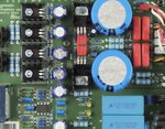
As the headphone amp below from start manufactured by a big german brand has BYV27 (R301 - R304) bypassed with 0,1uF (C301 - C304), are you telling this is not a good design? Should there be an improvement if those bypass caps being removed, maybe?

Power stage schematic for headphone amp.jpg

BYV27 Headphone amp.jpg
 

Fast diodes are no different for audio applications than 'slow' ones. Faster does not make them better any more than fitting a jet engine to a bicycle makes it quicker. Each type of diode has it's merits, in this case all the components after the diodes in the PSU are for filtering and regulating the output, it really makes little difference what you put in to them.

There is some sense in placing capacitors across the diodes but it has nothing to do with the audio quality or noise level whatsoever. Under some circumstances, probably not in this case, the reversal of voltage during the AC cycle of the incoming power can cause a very brief spike in current. That in turn under some circumstances can cause background buzzing on low frequency AM radio. Fast diodes tend to be worse in this respect! Adding a small capacitor can soften the spike and reduce the interference it produces but when used that way, it is generally better to use capacitors that exhibit low impedance at higher frequencies and low value ceramic types would work better than the ones shown. A 1nF ceramic is normally more than adequate but good layout and a mains input filter would be more effective anyway.

Brian.
 

there will always be a small amount of ringing when the diodes turn off - less for faster diodes, putting 100n in parallel with the slow diodes will mean there will be some ringing between the diode and the cap with the wiring inductance in between them - hence RC snubbers across the diodes are best if you really want to get rid of any small ringing - unless to use a scope to see what is going on then all is speculation as to the effect of just adding caps...
 

Putting capacitors across rectifier diodes is old-school, it lowers the ringing resonant frequency but does lower spike amplitude, so it does protect the diodes from transients.
You can get MHz switching hash from rectifier diodes, the use of ultra-fast 25nsec BYV27 is more of an audio fad.

I find best is a single RC snubber across a power transformer's secondary (not each diode) tames ringing and spikes from its leakage inductance. It pretty easy to scope the waveform there to see for yourself.

SMPS use an RC snubber across each rectifier diode though, I'm not sure if there is a difference between the two locations.
 

Ok, here´s a link about this Snubber you refer to (using a capacitor with a resistor in series before the rectifiers):

https://diyaudioheaven.wordpress.com/tutorials/power-supplies/snubbering/

For my schematic; If I remove C301 - C304 and replace them with only one capacitor with a resistor in series between the transformers secondary AC, should they be soldered directly between and after the heat fuses RF1/RF2?

As there are 15VAC for secondary, should a 100nF with a 10Ohm resistor be fine or are there any better values?

And how much Voltage should the snubber cap been rated at and what Wattage should the resistor be?`

Should a MKP or Ceramic do best for this snubber?

Also, as I use an EMI(?) filter from a PC Power Supply 230VAC primary side; may the snubber mod interact with this filter so only one of them should be used, or is it ok to combine them?
 
Last edited:

I took some 60Hz rectifier snubber measurements from both a homemade DAC and cheap chinese clone Lehmann headphone amp, similar to OP's project, and some breadboard variations.
For the Lehmann clone, transformer is Hammond 166J28 28VCT 1A, split-bobbin design, stock is four 0.1uF MKT across each (slow) 1N4004 rectifier, into 10,000uF filter caps for +/-18.5VDC typ. to the Vregs.
For the DAC which uses Hammond 166G25 25VCT 0.5A, split-bobbin design, four fast-recovery BYV26E rectifiers, into 3,300uF filter caps for +/-18.5VDC typ. to the Vregs. No capacitors across the transformer secondary or rectifiers. Very hard to see any recovery spikes on the scope, although they are still there.

With no capacitors at all, no ringing but a large fast spike about 20-30Vpk:
No caps_xfmr_secondary TEK00027.PNG

Lowest cost but terrible for ringing is a capacitor right across the transformer secondary, or across each rectifier diode. OK for a car battery charger from 1976 but no good for a quiet PSU:
100nF across secondary TEK00032.PNG

RC snubber alone across the transformer secondary, I found 280-630R and 10-100nF was critically damped. A lower value of snubber resistor, i.e. 10R is too low and did not lower the circuit's Q so there is lots of ringing. 100nF is also on the huge side.
Best RC snubber tuning 47nF 370R TEK00029.PNG

So my findings- fast-recovery diodes give a much smaller bump to the leakage inductance, and an RC snubber across the transformer tames the switching transients. The snubber values depend on the power transformer used and for audio 10-30VA around 28VAC like you'd find in a +/-15V power supply, around 33nF and 330R 1/2W. The cap doesn't matter if film or ceramic, although X7R have a large voltage coefficient. I use boxed MKT film caps rated 100VAC at least triple the operating voltage.

All this is relevant for a low noise mains PSU because the rectifier switching transients radiate EMI in the wiring and can walk through an electrolytic filter capacitor as their ESL is significant at RF frequencies. A linear Vreg has only a few kHz bandwidth.
 

snubbers across each diode allow you to increase the total snubber power to round off the sharp edges ... also it is right where the high dv/dt is generated ...
 

I do not doubt any of the technical explanations about diode recovery time and how to snub the spike but I do have reservations about how relevant it is in this situation. We are talking about a medium power audio amplifier with relatively low sensitivity and a symmetrical power supply. I really can't see how it would make a scrap of difference whether the ringing is optimally damped or not in this application.

Brian.
 

Hi,

I agree with you, Brian.

Thats HIGH END AUDIO PHILIOSOPHY.
Even if some one just says there is a snubber included ... many people will "hear", or at least "feel" the difference.
Usually such tests fail in double-blind experiments.

If it it does not bring a benefit, it at least does not harm. (Like globules for an electronic circuit).

****
But I´m not against this kind of improvement.
I sometimes do such improvements on my own. Maybe just to give me the feeling that I have designed a more perfect circuit.


Klaus


119kHz - that's pretty good - agreed the odds of the diode noise making any perceived difference to anything are pretty close to nil ( 1 / googolplex )

unless there is a very susceptible ckt nearby ...
 

Status
Not open for further replies.

Part and Inventory Search

Welcome to EDABoard.com

Sponsor

Back
Top