Dots
Newbie level 4

Hi
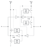
I am working with TXB0106 level translator (datasheet). While doing design, I came across page 12 in which an architecture of an I/O cell is displayed as shown below.

In page 14, it's stated that during output transition from high to low, and vice versa, output impedance will be 50 ohm. From the picture above, I understand that after one shot signal times out, the appropriate transistor will turn off and the output will be driven by the second stage inverter with an output impedance of 4 Kohm.
Let's say that I'm sending a high to low signal from B side and hoping to read low signal on A side. On the A side, there's an input on an unnamed module with a 40 Kohm pull up resistor. A high to low transition on B side will be inverted to high again by the first inverter in order to trigger T4 via the one shot circuit. After T4 is triggered, a low impedance (50 ohm) path will be connected between ground and input pin on the module, creating a voltage divider between 40 Kohm and 50 ohm, and thus it will read low on this pin.
Now, when the one shot signal times out, T4 will turn off and thus cutting connection between module's pin to ground. In this case, how can the module's pin keep reading low when there's no connection to ground? am I right in seeing that the second inverter would provide this path, sinking current from module's pin via a 4 Kohm impedance?
I am working with TXB0106 level translator (datasheet). While doing design, I came across page 12 in which an architecture of an I/O cell is displayed as shown below.

In page 14, it's stated that during output transition from high to low, and vice versa, output impedance will be 50 ohm. From the picture above, I understand that after one shot signal times out, the appropriate transistor will turn off and the output will be driven by the second stage inverter with an output impedance of 4 Kohm.
Let's say that I'm sending a high to low signal from B side and hoping to read low signal on A side. On the A side, there's an input on an unnamed module with a 40 Kohm pull up resistor. A high to low transition on B side will be inverted to high again by the first inverter in order to trigger T4 via the one shot circuit. After T4 is triggered, a low impedance (50 ohm) path will be connected between ground and input pin on the module, creating a voltage divider between 40 Kohm and 50 ohm, and thus it will read low on this pin.
Now, when the one shot signal times out, T4 will turn off and thus cutting connection between module's pin to ground. In this case, how can the module's pin keep reading low when there's no connection to ground? am I right in seeing that the second inverter would provide this path, sinking current from module's pin via a 4 Kohm impedance?
