Continue to Site

Welcome to EDAboard.com

Welcome to our site! EDAboard.com is an international Electronics Discussion Forum focused on EDA software, circuits, schematics, books, theory, papers, asic, pld, 8051, DSP, Network, RF, Analog Design, PCB, Service Manuals... and a whole lot more! To participate you need to register. Registration is free. Click here to register now.

Read pulses from rotary encoder - Arm 7 lpc 2148

Status
Not open for further replies.

Nikolica

Newbie level 6
Newbie level 6
Joined
Jul 22, 2014
Messages
13
Helped
0
Reputation
0
Reaction score
0
Trophy points
1
Activity points
98
This is my code for capture egde from rotary encoder. Can anyone help me .
The problem is in code.

Code:
#define 	MOJTIP (unsigned char *)
#define 	MR0I_FLAG (1<<0)
/**********************************************/
void UART0_Init(void);
void UART0_Ispisi(unsigned char vrednost);
void UART0_Ispisi_Tekst(unsigned char msg[]);
unsigned char UART0_Citaj(void);
unsigned char UART0_CitajINT(void);
void UART0_Ispisi_NumberINT(unsigned int num[]);
/**********************************************/
__irq void T0ISR(void);
/**********************************************/
char jbuffer[20] = { 0 };
int jirq=0;
int value2;
/**********************************************/

/*Main Function Starts*/
int main(void)
{
PINSEL0 = 0x00000020; // Enable pin 0.2 as capture channel0
T0PR   = 1500; 
T0TCR   = 0x00000002; // Reset counter and prescaler
T0CCR = 0x00000005; // Capture on rising edge of channel 0
T0TCR = 0x00000001; // enable timer 
VICVectAddr4 = (unsigned)T0ISR; // Set the timer ISR vector address
VICVectCntl4 = 0x00000024;   // Set channel
VICIntEnable = 0x00000010;     // Enable the interrupt 
UART0_Init();
	while(1)	
	{		
	T0TCR = 0x001;	
			UART0_Ispisi('x');
if(value2>0)
{	
		snprintf(jbuffer,20,"%d",jirq);		
		UART0_Ispisi_Tekst(MOJTIP "\n\t");		
		UART0_Ispisi_Tekst(MOJTIP jbuffer);
}		
	}
}
__irq void T0ISR(void) // __irq void T0ISR(void);
{
static int value;
	UART0_Ispisi('b');
value = T0CR0; // read the capture value
	value2=value;//	sprintf(jbuffer,"n%d",(unsigned int)value); //	UART0_Ispisi_Tekst(MOJTIP jbuffer);
if(value>0)
{
	jirq++;
	UART0_Ispisi('c');
}
	T0IR |= 0x00000001; // Clear match 0 interrupt
	VICVectAddr = 0x00000000; // Dummy write to signal end of
}
void UART0_Init(void)
{
	PINSEL0 = 0x00000005;				
	U0LCR = 0x83;	
	U0DLM = 0x00;
	U0DLL = 0x62;		//Baud Rate - 9600
	U0LCR = 0x03;									
}
void UART0_Ispisi(unsigned char vrednost)
{
	while(!(U0LSR&0x20));					
	U0THR = vrednost;
}
void UART0_Ispisi_Tekst(unsigned char msg[])
{
	while(*msg)
	{
		UART0_Ispisi(*msg);
		msg++;
	}
}
unsigned char UART0_Citaj(void)
{
 

Hi,

What is the "problem"?
Without a description what you expect, and what happens instead, you will get no help.
If there is an error with your code... what have you done to find the error?

Klaus
 

Thank you Klaus for your reply.
The problem is that the processor doesn't want to read impulses from port p0.2. So that means that program is not getting (going) in IRQ routine. I want to rotate easily axle of rotary encoder, so it can count impulses who are received on CAP periphery of encoder, so it can count those impulses and printing numbers on terminal. For a beginning I did this, so I should know where the problem is. And I got in touch with you.
 
Last edited:

Hi,

With your very poor and un-technical description it's like looking into a crystal ball.

What is CAP periferal?
Did you check hardware?
Did you verify encoder signals? Are they clean and debounced?
Did you verify isr functionality?
Did you verify uart functionality?
What do you expect t0cr0 to be?

Klaus
 

Hi

I checked hardware. It's all alright. With encoder I have no problems because I tested his work on oscilloscope. The signals are clean. I think that the problem is in ISR routine, that's why I set it to show me some sort of characters. Uart is functioning great, it shows me what I want, for example the value of changeable 'value', or 'jirq', but as a number 0.
T0CRO ??? It's a register whom letting me to turn on counting or to delete counter.
Thank you Klaus
 

Hi,

this information of your post#5 should have been in post#1...to save 21 hours.

*******

Uart is functioning great, it shows me what I want
You are receiving "x", "b" and "c"?
but your variables are shown as 0?

Klaus
 

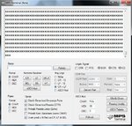
edabord.jpg

When I start up program, he print xxxx on terminal. Remark : he also print 'x' with rotating axle of rotary encoder.
 

Hi,

things are clearing up.

Your main loop may be vary fast. At each run it tries to output an "x". But UART may be slower than the main loop and it may miss data to transmit.

--> try to include a counter in main loop and output an "x" only every 1000 main loop runs. (you could adjust on this value)

*****

while "x", "b" and "c" are characters that can be shown in your terminal on the PC. The variable values are not.
these variable values have to be converted to ASCII strings.

*****

Klaus
 

When I start up program, he print xxxx on terminal. Remark : he also print 'x' with rotating axle of rotary encoder.

As you are printing the character 'x'
Code:
        while(1)	
	{		
	T0TCR = 0x001;	
			UART0_Ispisi('x');

If you want to send the encoder number you need to use. void UART0_Ispisi_NumberINT(unsigned int num[]); .
 

Friends, thank you for your answers, but I can disable line with printing 'x'. Problem is not with 'x' . Problem is with irq or timer initialization. I write line with jirq++, he can print a some character if j>1 .
I think that problem is not in printing
 

Hi,

i did not say it is printing, but UART interface is too slow to transmit all data you want to send.

in your picture, there are only "x" and nothing else. So still the question is: did you verify ISR functionality?

Klaus
 

Hi,

i did not say it is printing, but UART interface is too slow to transmit all data you want to send.

in your picture, there are only "x" and nothing else. So still the question is: did you verify ISR functionality?

Klaus

Can I do it with switching on/off led, like if impulse come to Arm, turn on led in place of
printing 'x' ? I think that my program not go on ISR !!! Because, I was disabled line with printing 'x'.. And I very slowly rotate axle of encoder, between, I rotate third channel, not A and B, than Z (index) marking signal.
 

yes you can check it that way its good for debugging.

Code:
#include <lpc214x.h>

#define PLOCK 0x00000400
#define MR0I (1<<0) //Interrupt When TC matches MR0
#define MR0R (1<<1) //Reset TC when TC matches MR0

#define DELAY_MS 500 //0.5 Seconds Delay
#define PRESCALE 60000 //60000 PCLK clock cycles to increment TC by 1

void delayMS(unsigned int milliseconds);
void initClocks(void);
void initTimer0(void);
__irq void T0ISR(void);

void setupPLL0(void);
void feedSeq(void);
void connectPLL0(void);


int main(void)
{
    initClocks(); //Initialize CPU and Peripheral Clocks @ 60Mhz
    initTimer0(); //Initialize Timer0

    IO0DIR = 0xFFFFFFFF; //Configure all pins on Port 0 as Output
    IO0PIN = 0xF;
   
    T0TCR = 0x01; //Enable timer

    while(1); //Infinite Idle Loop

    //return 0; //normally this wont execute ever   :P
}

void initTimer0(void)
{
    /*Assuming that PLL0 has been setup with CCLK = 60Mhz and PCLK also = 60Mhz.*/
   
    //----------Configure Timer0-------------

    T0CTCR = 0x0;

    T0PR = PRESCALE-1; //(Value in Decimal!) - Increment T0TC at every 60000 clock cycles
                   //Count begins from zero hence subtracting 1
                   //60000 clock cycles @60Mhz = 1 mS

    T0MR0 = DELAY_MS-1; //(Value in Decimal!) Zero Indexed Count - hence subtracting 1
   
    T0MCR = MR0I | MR0R; //Set bit0 & bit1 to High which is to : Interrupt & Reset TC on MR0  

    //----------Setup Timer0 Interrupt-------------

    VICVectAddr4 = (unsigned )T0ISR; //Pointer Interrupt Function (ISR)

    VICVectCntl4 = 0x20 | 4; //0x20 (i.e bit5 = 1) -> to enable Vectored IRQ slot
                               //0x4 (bit[4:0]) -> this the source number - here its timer0 which has VIC channel mask # as 4
                               //You can get the VIC Channel number from Lpc214x manual R2 - pg 58 / sec 5.5
   
    VICIntEnable = 0x10; //Enable timer0 int

    T0TCR = 0x02; //Reset Timer
}

__irq void T0ISR(void)
{
    long int regVal;
    regVal = T0IR; //Read current IR value
       
    IO0PIN = ~IO0PIN; //Toggle the state of the Pins

    T0IR = regVal; //Write back to IR to clear Interrupt Flag
    VICVectAddr = 0x0; //This is to signal end of interrupt execution
}

void initClocks(void)
{
    setupPLL0();
    feedSeq(); //sequence for locking PLL to desired freq.
    connectPLL0();
    feedSeq(); //sequence for connecting the PLL as system clock
   
    //SysClock is now ticking @ 60Mhz!
       
    VPBDIV = 0x01; // PCLK is same as CCLK i.e 60Mhz

    //PLL0 Now configured!
}

//---------PLL Related Functions :---------------

//Using PLL settings as shown in : http://www.ocfreaks.com/lpc214x-pll-tutorial-for-cpu-and-peripheral-clock/

void setupPLL0(void)
{
    //Note : Assuming 12Mhz Xtal is connected to LPC2148.
   
    PLL0CON = 0x01; // PPLE=1 & PPLC=0 so it will be enabled
                    // but not connected after FEED sequence

    PLL0CFG = 0x24; // set the multipler to 5 (i.e actually 4)
                    // i.e 12x5 = 60 Mhz (M - 1 = 4)!!!
                    // Set P=2 since we want FCCO in range!!!
                    // So , Assign PSEL =01 in PLL0CFG as per the table.
}

void feedSeq(void)
{
    PLL0FEED = 0xAA;
    PLL0FEED = 0x55;
}

void connectPLL0(void)
{
    // check whether PLL has locked on to the  desired freq by reading the lock bit
    // in the PPL0STAT register

    while( !( PLL0STAT & PLOCK ));

    // now enable(again) and connect
    PLL0CON = 0x03;
}
 

Hi,

Can I do it with switching on/off led, like if impulse come to Arm, turn on led in place ofprinting 'x' ?
For sure you can.

I think that my program not go on ISR !!! Because, I was disabled line with printing 'x'.
this means you never received a "b" or a "c". Is this true?

If it is true, then i recommend:
(driving a LED from main loop will give no additional information, because we already know that main loop is running)
Therfore i´d drive a LED in ISR. Mind that ISR is short in time, maybe the eye can not recogize it. Therfore test the signal with a scope.

***
The encoder has three outputs: A, B and Z. When you rotate the encoder all signals are working (Z only one short pulse per revolution)
Where are those three lines connected to your LPC2148?

***

with PINSEL0 in main loop you set p0.2 function to "capture 0.0"
but after that in uart0_init you overwrite it to be a PGIO again. --> here either you need to write "0x00000025" or better you use a read-modofy-write operation on the register.

Klaus
 
  • Like
Reactions: Ravi28

    Ravi28

    Points: 2
    Helpful Answer Positive Rating
__irq void T0ISR(void) // __irq void T0ISR(void);
{
static int value;
value = T0CR0;
if( T0CR0 & MR0I_FLAG )
{
IO0SET=0XFF000;
jirq++;
}
IO0SET=0XFF000;

T0IR |= 0x00000001; // Clear match 0 interrupt
VICVectAddr = 0x00000000; // Dummy write to signal end of
}


Friends, now ... When I connect encoder with arm7, led is switching on... But, if I disconect encoder, led is turnend off, and when I touch P0.02 with wires of encoder, he will turned on diodes... What is the mistake ?
 

Klaus is correct about the PINSEL0 incorrect value in subroutine void UART0_Init(void)

it rather be like this

PINSEL0=0x00000025;

or use bitwise operations (read-modofy-write) on the register

PINSEL0|=0x00000005; // updating PINSEL0 bit 0 and bit 2 as TXD0 & RXD0 pins for UART0.

Hope this solves the problem.
 

As you are printing the character 'x'
Code:
        while(1)	
	{		
	T0TCR = 0x001;	
			UART0_Ispisi('x');

If you want to send the encoder number you need to use. void UART0_Ispisi_NumberINT(unsigned int num[]); .
I do it, but this not print me number ... and I try with snprintf , and this is ok.
Capture - IRQ.jpg
How doesn't want to see this IF loop in the IRQ function? How can I make it to do me only changes? I'm his configure to capture the rising edge of the pulse. Something like this video :
Code:
https://www.youtube.com/watch?v=2puhIong-cs
Code:
https://www.youtube.com/watch?v=OYbgCwhfITw
 

Status
Not open for further replies.

Part and Inventory Search

Welcome to EDABoard.com

Sponsor

Back
Top