matt93
Newbie level 1

I've reached one of the final stages (Step 12: Wiring: Power) of this GamePi project https://www.instructables.com/…/GamePi-the-Handheld-Emulat…/
This involves wiring up a battery to the PCB of a power bank, and also wiring up a DPDT slide switch to the PCB, which then connects directly to pins 2 and 5 of a Raspberry Pi, and is used to power it on and off. The power bank which was recommended for the project is no longer available, but the creator recommended this PCB https://de.aliexpress.com/item/32792636437.html which I ordered.
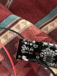
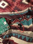
The electronics circuitry of the PCB is different from the one pictured in the instructable, and I'm having problems working out how this should be wired. I've soldered and tested the battery fine, but it's very unclear what to do with the slide switch. The PCB already has a push button on/off switch soldered on, which I assumed I would have to desolder from the board. I don't know how to solder the slide switch to the board though, as there appear to be 4 solder points, and I don't know which ones to solder to? The diagram on the Instructable is unclear enough as it is! I've tried combinations of these, but can't seem to get the slide switch to power the board on and off, or even to power the Pi at all. Am I going about this wrong? I've attached pictures, and can give more information/details. The negative wire coming out of S1 is just one of my attempts, but I assume that the switch needs to be soldered to two of these points, one of which may be the one I've soldered to.
I'd really appreciate any help, as I'm right at the end of this project now, and want to get it finished!

