Terminator3
Advanced Member level 3

I am trying to calculate radiation pattern of a patch antenna using this formulas:
(**broken link removed**)
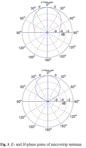
Here is radiation patterns for E and H planes:

As you can see E-plane red curve looks not right (as i think).
I searched for some radiation pattern images in internet and found out that E-plane and H-plane pattern does not differ so much as on my image. Also i checked formulas many times and all seems to be ok. What's wrong here with red curve?
It can be directly pasted to freeware program called SpeqMath.C=299792458;
Freq=10.525*10^9;
'wavelength in free space (in mm)
L0=1000*C/Freq
L0 = 28.48384399
'width of patch (mm / mm)
w=8.8/L0
w = 0.308947065
'length of patch (between radiating edges)
l=6.03/L0
l = 0.211698955
'substrate height
h=1.6/L0
h = 0.056172194
Hplane(x)=Sin( (2*Pi*w/2) *Cos(x) ) / ( (2*Pi*w/2)*Cos(x)) *Sin(x)
Function Hplane(x) is defined
Eplane(x)=Sin( (2*Pi*h/2) *Cos(x) ) / ( (2*Pi*h/2)*Cos(x)) *Cos((2*Pi*l/2)*Cos(x) )
Function Eplane(x) is defined
Plot(20*Log10(Hplane(Pi/2+x*Pi/180)),xMin=-90,xMax=90)
Plot done
Plot(20*Log10(Eplane(Pi/2+x*Pi/180)),xMin=-90,xMax=90)
Plot done
(**broken link removed**)
Here is radiation patterns for E and H planes:
As you can see E-plane red curve looks not right (as i think).
I searched for some radiation pattern images in internet and found out that E-plane and H-plane pattern does not differ so much as on my image. Also i checked formulas many times and all seems to be ok. What's wrong here with red curve?