Continue to Site

Welcome to EDAboard.com

Welcome to our site! EDAboard.com is an international Electronics Discussion Forum focused on EDA software, circuits, schematics, books, theory, papers, asic, pld, 8051, DSP, Network, RF, Analog Design, PCB, Service Manuals... and a whole lot more! To participate you need to register. Registration is free. Click here to register now.

R and C values for a bldc card

Status
Not open for further replies.

jmx66

Member level 5
Member level 5
Joined
Nov 16, 2010
Messages
93
Helped
0
Reputation
0
Reaction score
1
Trophy points
1,288
Location
France
Activity points
2,045
Hi all,

Last query before, - i hope - etching and drilling the board.

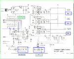
In fact , on my burnt bldcd card, there's a part with C and R.

Schematic is my true card.

After reading MC33035 and 33039, then AN 1046D , i don't understand purpose of these components.

If someone could give me the answer,and also how to compute them, would be great.

Thanks a lot.

jm
 

Attachments

  • Brusless-DC-Motor-Controller-MC33035-D.PDF
    526.3 KB · Views: 103
  • MC33039-Datasheet.pdf
    101.5 KB · Views: 90
  • numérisation0003-modif-1.png
    numérisation0003-modif-1.png
    1.1 MB · Views: 126
  • RC-MC33035-33039.png
    RC-MC33035-33039.png
    17.9 KB · Views: 122

You mean the R and C connected through JP1? They set the output current limit and this way adjsut the PWM setpoint. The limit comparator has a threshold of about 100 mV, the sense resistor is shown with a 0.012 ohm value. So without a resistor connected to JP1, the current limit is set to about 8.3 A. Connecting R35 creates a 1:1 divider and doubles the current threshold. The capacitors are used to prevent current spikes to trigger the comparator.
 
  • Like
Reactions: jmx66

    jmx66

    Points: 2
    Helpful Answer Positive Rating
Hi FvM,

Thanks for your really fast reply - about less than 5 minutes after post !!!!! -, in fact, my query is about R6 to R11 with their capacitors.( see num-risation0003-modif-1-png )

I draw a schematic - black scheme - and their labels are R1 -> R6 and C1 - > C6 .

And i don't know how to math R and C values...

Thanks a lot.

jm
 

Do you know the expected maximum output currents? As far as I understand, the current will be normally ruled by the PWM according to the speed setpoint. The current limit should only trigger in abnormal situations, e.g. a blocked motor. The capacitor dimensioning is discussed in datasheet Fig. 26. The actual current threshold is defined by 100 mV/0.012 ohm * (Rx+R35)/R35, where Rx is the resistor connected by JP1.
 
  • Like
Reactions: jmx66

    jmx66

    Points: 2
    Helpful Answer Positive Rating
Hi FvM,

Thanks a lot for your quick replies.

In fact , i 've just modified the original scheme , because i didn't ask question very clearly, with right scheme... Apologies.

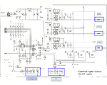
So my query is about R6 to R11 and C11 to C16 see grey box with inside

" Values for R6 to R11

C11 to C16 "

Middle left side

I really read datasheet and AN, but with my mechanical background, didn't really how to math these values, hence my answer!!!!!


Thanks a lot.

jm

Ps: Now going to bed, tomorrow five o' clock in the morning.....
 

Attachments

  • R-and-C-Values.png
    R-and-C-Values.png
    1.1 MB · Views: 117

O.K., I didn't notice this additional point. That's more easy. The resistors are simply pull-ups to be used with input switches and the open collector hall-effect sensor outputs. There are already pull-ups inside the IC (20k and 40k according to the datasheet). I would e.g. place 10 k for each external resistors, and a capacitor around 1 nF to filter possible spikes. But I'm not sure, if they are needed. You should also check the halls sensor specification for the specified ouput load.
 
  • Like
Reactions: jmx66

    jmx66

    Points: 2
    Helpful Answer Positive Rating
Thanks a lot FvM for your clear replies.

Really great .

jm
 

Status
Not open for further replies.

Similar threads

Part and Inventory Search

Welcome to EDABoard.com

Sponsor

Back
Top