Continue to Site

Welcome to EDAboard.com

Welcome to our site! EDAboard.com is an international Electronics Discussion Forum focused on EDA software, circuits, schematics, books, theory, papers, asic, pld, 8051, DSP, Network, RF, Analog Design, PCB, Service Manuals... and a whole lot more! To participate you need to register. Registration is free. Click here to register now.

Questions regarding Bandgap reference

Status
Not open for further replies.

HCHEN

Newbie level 2
Newbie level 2
Joined
May 13, 2013
Messages
2
Helped
0
Reputation
0
Reaction score
0
Trophy points
1,281
Activity points
1,300
Hi, I like some help with the following questions (malcovati bicmos bandgap design):

1) Where does the non-linear term in bandgap circuit come from?
2) For malcovati bicmos bandgap design to work, BJT matching was set to 1:24 if I were to change it to 24:1 will the bandgap design still work?
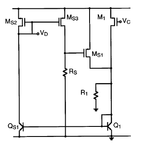
3) For malcovati bicmos bandgap design, instead of connecting the startup circuit to the negative side of the differential pair, can i connect it to the positive side of the differential pair?
4) How does the startup circuit work stage by stage?
5) Why does the startup circuit have to be turned off, when the bandgap circuit is in normal operation operation?
6) Can i connect a resistive load directly to the output of the bandgap reference?
7) How do i determine that Rs>2R1 in the startup circuit?
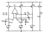
bandgap design.png
bandgap circuit
start up.png
start-up circuit
 

HCHEN,

1) non-linear term comes from the non-linearities of the bipolar transistor. VBE voltage does not decrease perfectly linear with temperature.
2) it will not work. Q2 should have larger area
6) No. You cannot connected a resistor, since it will change the output voltage.
 
  • Like
Reactions: HCHEN

    HCHEN

    Points: 2
    Helpful Answer Positive Rating
HCHEN,

1) non-linear term comes from the non-linearities of the bipolar transistor. VBE voltage does not decrease perfectly linear with temperature.
2) it will not work. Q2 should have larger area
6) No. You cannot connected a resistor, since it will change the output voltage.

Hi palmeiras,
so for
1) the bandgap design only solves the linear term in Q1 and Q2?
2) why wont it work? This question was asked by my professor and I dunno know how to answer it.
6) so if I wanted to connect a resistive load what must i add after the output reference voltage to ensure that my output reference voltage wont change.
 

1) Vref=K1*DeltaVbe+K2*Vt ,we know Derivative of Vt to Temp is current nubmer while Derivative of DeltaVbe is not .
2) Q2 must be set bigger than Q1 to make sure there is a positive voltage for R1.it is not necessery to be set 24:1,you can make it 8:1 and so on
6) you can't load a res randomly as the current M3 have been setted by M1 and M2


Hi, I like some help with the following questions (malcovati bicmos bandgap design):

1) Where does the non-linear term in bandgap circuit come from?
2) For malcovati bicmos bandgap design to work, BJT matching was set to 1:24 if I were to change it to 24:1 will the bandgap design still work?
3) For malcovati bicmos bandgap design, instead of connecting the startup circuit to the negative side of the differential pair, can i connect it to the positive side of the differential pair?
4) How does the startup circuit work stage by stage?
5) Why does the startup circuit have to be turned off, when the bandgap circuit is in normal operation operation?
6) Can i connect a resistive load directly to the output of the bandgap reference?
7) How do i determine that Rs>2R1 in the startup circuit?

View attachment 90971
bandgap circuit
View attachment 90972
start-up circuit
 
  • Like
Reactions: HCHEN

    HCHEN

    Points: 2
    Helpful Answer Positive Rating
Hi HCHEN,
1) the first order BGR is a balanced sum of VBE and VTH. VTH only compensates the linear part of VBE. The non-linear terms of VBE stays uncompensated, the reason why you see the typical curvature. There are several methods to compensated this non-linearity. These type of architectures are called "curvature correction" or "curvature compensated". It added an non-linear term with opposite TC.
2) The reason is because the current defined across the resistor is given by I = UT*ln(aspect ratio) of Q2/Q1. So considering both branches with equal current, Q2 must be larger than Q1. Is it clear?
3) you need to isolate the output reference, for instance, adding a buffer. An amplifier in a feedback configuration.
 

Status
Not open for further replies.

Part and Inventory Search

Welcome to EDABoard.com

Sponsor

Back
Top