Continue to Site

Welcome to EDAboard.com

Welcome to our site! EDAboard.com is an international Electronics Discussion Forum focused on EDA software, circuits, schematics, books, theory, papers, asic, pld, 8051, DSP, Network, RF, Analog Design, PCB, Service Manuals... and a whole lot more! To participate you need to register. Registration is free. Click here to register now.

Questions about switched cap filter

Status
Not open for further replies.

sxb416

Junior Member level 1
Joined
Mar 13, 2008
Messages
17
Helped
4
Reputation
8
Reaction score
3
Trophy points
1,283
Activity points
1,398
I have some quention about swtiched cap filter.
1.what can i care about the amp design except SR, dc gain ,GBW?
2.I design a 2nd biiquad filter,
but the gain of the filter can't reach the 0db,I am sure the cap value is ok.
what can i do,advance the amp or change the cap value.
thank you
 

Re: about active filter

In short: Your circuit does not work as wanted.
But, do you really believe we can give you some help without knowing some details? (filter topology, S/C block realization, clock frequency, design bandwidth, opamp type...)
 

Re: about active filter

The details is as follow :
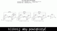
1.The filter topology is in the figure, and the sample freq is 32K,

2.the opamp is full differentail ota,the type is the common 2nd ota add the resistor common mode feedback. the gain is 75db,the gbw is 1.8Meg,the SR is
4v/us.
 

Re: about active filter

sxb416 said:
The details is as follow :
1.The filter topology is in the figure, and the sample freq is 32K,

2.the opamp is full differentail ota,the type is the common 2nd ota add the resistor common mode feedback. the gain is 75db,the gbw is 1.8Meg,the SR is
4v/us.

The circuit shown (is it really necessary to compress the file?) is derived from "Filter solutions" and is based on opamps. Please note that an opamp is not an OTA ("the opamp is full differential ota").
But - how should we know if there was any error transferring the opamp into the ota topology? For example, what did you do with the last stage?
 

Re: about active filter

Thanks for your reply,but I don't understand your mean.
First, the solution filter use the opamps for the filter.But the load of opa is a capcitance or huge resistor .why I need a opamp ( ota+buffer)?
Second,when I use a full differential ota simulate the filter,the pole and zero is right,and I only need to adjust the gain,but I use a single-end cascode amp ,I can't get the right waveform,wrong pole or zero is shown.
I am very puzzled.
 

about active filter

You are talking all the time about a circuit, you never showed!
 

Re: about active filter

the figure is as follow.
 

Re: about active filter

...why I need a opamp ( ota+buffer)?
Who gave you the advice to use opamps ?

...,the pole and zero is right,and I only need to adjust the gain,
I can't get the right waveform,wrong pole or zero is shown.
Sounds contradictory.

I am very puzzled.
Me too.
 

Status
Not open for further replies.

Similar threads

Part and Inventory Search

Welcome to EDABoard.com

Sponsor

Back
Top