Continue to Site

Welcome to EDAboard.com

Welcome to our site! EDAboard.com is an international Electronics Discussion Forum focused on EDA software, circuits, schematics, books, theory, papers, asic, pld, 8051, DSP, Network, RF, Analog Design, PCB, Service Manuals... and a whole lot more! To participate you need to register. Registration is free. Click here to register now.

Questions about LEDs and Circuit Design/thoughts

Status
Not open for further replies.

MostlyHarmless

Newbie level 4
Newbie level 4
Joined
Jun 15, 2013
Messages
7
Helped
0
Reputation
0
Reaction score
0
Trophy points
1
Activity points
69
Hi All,

Hopefully this is the right place, as this certainly is a Hobby Circuit/Small project issue :)

Not sure where to begin. Been trying to figure out how to do circuit for LED's that will take a variable voltage and light up a series of LED's in a progressive way.
I.e I want the LED's to come on when the output voltage goes past certain points. This is for my daughters science project where kids will turn a crank handle connected to a motor, will generate DC voltage. Rather than all the LED's coming on at once, wanted it to appear in stages. I used to do circuit design and messing around with digital and analogue electronics, but alas cannot remember what it is I am looking for or at. For some reason I keep thinking of having like 5 LEDs in an array, then a capacitor feeding the next array (it requiring enough juice to power the 1st array and charge the capacitor enough?) Might be completely wrong :)

Any pointers gratefully received, hopefully I have explained it right.

R
 

If they are still available there is a device called an LM3914 which had a single voltage input and 10 LED driver outputs. The LEDs operated as a bar graph or single 'peak' indicator. That sounds to be exactly what you need. They are quite old devices now and if not available there are other options:

1. a stepped window comparator - basically a chain of resistors across a stable supply voltage, each junction has a proprtion of the full voltage on it. You use a comparator circuit for each LED that compares one of the steps with the input voltage and lights it's LED when the input exceeds the step voltage. Easy to build but uses quite a lot of components.

2. If you are into writing software, most microcontrolers have built in analog to digital converters (ADCs) which you can use to measure the voltage and then in software as the value exceeds thresholds you have decided, it turns on an LED connected to one of the port pins. This uses very few components because it does the comparisons in software but it does require you write some code. I would qualify that by saying the code is very simple!

I think the capacitor idea is a non-starter.

Where are you? I might be able to advise on where LM3914s can still be purchased.

Brian.
 

Thanks Guys! Good set of links there Peter, ty.

Betwixt, yes this is something very close to what I had in mind, although rather than a block of LED that would like up one by one, it would more like spelling out a name. so x volts = 1st letter, y volts = 2nd letter and so on. The "competition" would be to see if someone could light up the word :) I do have a raspberry pi, but I have yet to use the GPIO pins and am unsure of how much juice it could pump out. But I like this idea! I think it would be more interesting to make and program. So it would "detect" the voltage levels on one set, then once it reached a threshold it would send a command to switch the LED set on/off as the voltage raised/dropped? Sounds simple.. might have to use something like an arduino which has more power/ in's and out's. I would also need to step down the detection voltage quite a bit. don't want to blow up the Pi :)

Feasible?

R
 

I haven't got a Pi, I wish I had but I would never have the time to experiment with it! The idea is still the same though unless you want to take it a step further and actually output the font to draw the letters rather than just light up single LEDs. That would be far more complicated and also introduce the problem of different length names.

Actually driving the LEDs is no problem at all, you can either use a transistor and a couple of resistors to boost the current or you can use a driver array, a device like the ULN2803 has 8 high current drivers in it and can be driven directly from a logic signal, they are very inexpensive. Dropping the input votage is easy, just use a potential divider and for safety add a Zener diode across the input to limit it just in case something nasty creeps in.

I did something similar many years ago using a PIC processor, I think I used 12 LEDs driven from the port pins.

Brian.
 

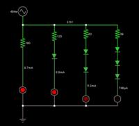
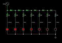
Here are two simple ways to generate a bargraph with led's.


No led's light until the supply voltage reaches their turn-on level (example, 1.7V for ordinary red type).

The second schematic is suitable for a greater range of volt levels. The resistor values must be selected to limit current to a safe level at maximum expected voltage.
 
The trouble with that design it it gradually turns the LEDs on rather than each abrupty lighting at fixed levels. For some applications it would be fine but to highlight letters one by one it would have difficulty, particularly if someone had a long name!

Brian.
 

I think if it meant that it was less digital and there was a direct correlation between effort going in and LED's being lit, that is fine. It looks a lot simpler!

I do have a couple of questions though if I may...

1) what are the blocking diodes in aid of? (I was guessing to make the motor only work one way, as if you turn it the other way you effectively are reversing the polarity?)
2) If the motor can generate between 0-50v @ ? amps, what considerations do I need to make regards the resistors? This is a parallel circuit right? If memory serves that means the source voltages stay the same but the total current increases? (as each resistor draws its own current?)
Just worried that putting such a variable voltage will blow the LED's.

Thanks for your help so far. I can feel myself getting the bug again :)

R
 

Simple design with resistors is ok with fixed maximum voltage, but if input voltage goes higher LEDs can be damaged.


Best regards,
Peter
 

They are not blocking diodes although they also have that effect. They are there because each (asuming they are ordinary siilcon diodes) needs about 0.6V across it before it conducts. The idea is that if one LED alone needs say 1.5V to light it, one with a single diode in series will need (1.5 + 0.6) = 2.1V , the next with two diodes will need 2.7V and so on. There are two drawbacks to the circuit though, one is that the LEDS do not light at full brightness one by one, the first starts dim, then the second starts dim with the first brighter and so on, you get a gradual decrease in brightness as you move along the chain. The other drawback is you have to cater for the current in all the LEDs, by the time the final one (with lots of diodes in series with it) has reached reasonable brightness, the first one may be puffing out smoke. Unfortunately, you can't just use different value resistors because they would have effect at all voltages and setting the value so the first is bright at full voltage would mean it hardly lit at low voltage.

If a gradual lighting along the chain is acceptable the circuit is OK but to make each LED come on at full brightness as the voltage increases would need a comparator as described earlier.

Brian.
 
Yeah OK, I see the flaw in the plan with that.

Well I did some testing and I connected the 2 motors I have here to a drill. one came from a printer (HP) and this seems to give out 5v with little or no effort. but quite low in amp.
the 2nd came from a golf trolley, spinning this didn't produce hardly any V, but amps was 5++. Figuring how much they would need to turn it to produce a an average seems to suggest that it would fit nicely in a low V range but with lots of amps. Ideal?

One drawback on using the Pi/Software, need to check we can actually get power to the board to run the software (not sure the stands have mains power :p)

Thanks for the help thus far. I will probably spend a little time figuring out some more bits and bobs and come back and ask some more questions if that's ok?

R
 

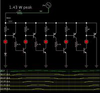
This design shows promise. Modified from the schematic at the website:


The bargraph network operates over a range of a few volts.

The 150 ohm resistor is there to reduce the supply voltage so that you get evenly-spaced turn on levels.

A windshield wiper motor might be suitable as a generator. I do not know what range of volt output you will get from spinning it. (My schematic shows 16V maximum supply voltage.)

For each led you could put a string of them to form characters. However the resistor values probably will need to be adjusted.
 
Would each of the LED's on that diagram represent an array of LED's? Should I put them in series or in parallel?

R
 

Also what type of transistors are you depicting there? Or are they the same as per the original you took it from?

R
 

They would either have to be single LEDs or you would have to use the same number of LEDs in each position. The LEDs are themselves used as voltage droppers so if they do not drop the same voltage, the difference in turn on voltages will be different in each stage. In general, never connect LEDs in parallel, at least without adding a series resistor to each individual LED. When wired across each other, the LED with the lowest turn on voltage will hog most of the current and their brightness will be uneven.

The transistor types are not really important, any general purpose PNP and NPN transistors should work but keep to the same types in each position.

A comparator based solution would still be better.

Brian.
 

The comparator solution being it measures voltage on one side and activates a bank of LED's on the other?

Yeah I kinda agree. both solutions have merit, just want to be in the best place to decide which I want or think will be best.

Thanks for the answer though :)

R
 

1.

I agree with Betwixt's replies. Whether you put led's in series or parallel, you will have to custom-adjust all values, if you wish to have evenly-spaced turn-on increments.

If you put led's in series, then your motor has to produce a higher range of volt output, to drive them.

With led's in parallel you may have wide variations in current draw.

2.

The 3914 is suitable. Its outputs can each drive one or two led's in parallel. Or, each output can turn on a transistor which drives several led's in parallel.

I have used the 3914 in bargraph voltmeters, where the supply can range between 0 and 16V. If it were to go too high you must regulate it to 25V.

3.

To create each letter, it may be easier (as far as electrical considerations) to use a single bright led (white or orange or yellow), installed inside a bottlecap 3/4 inch wide by 3/4 inch high. Cover its open end with a piece of paper which has a letter printed on it. The led's should be wide-beam.
 

Status
Not open for further replies.

Part and Inventory Search

Welcome to EDABoard.com

Sponsor

Back
Top