Continue to Site

Welcome to EDAboard.com

Welcome to our site! EDAboard.com is an international Electronics Discussion Forum focused on EDA software, circuits, schematics, books, theory, papers, asic, pld, 8051, DSP, Network, RF, Analog Design, PCB, Service Manuals... and a whole lot more! To participate you need to register. Registration is free. Click here to register now.

questions about bode plot for LC series circuit (two imaginary poles in Y axis)

Status
Not open for further replies.

bhl777

Full Member level 6
Full Member level 6
Joined
Sep 30, 2008
Messages
363
Helped
0
Reputation
0
Reaction score
0
Trophy points
1,296
Activity points
5,140
Hi everyone, if we have a LC circuit, L and C connect in series, one side of L is input and one side of C is ground. If the output voltage is between ground and the other side of C,
then we will have the transfer fucntion like T=1/(1+LC(S^2)), which means that the poles are in the imaginary axis.
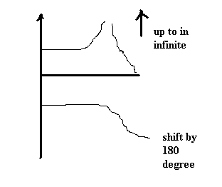
How can we draw the bode plot for this? Thank you very much!
 

Here is:
48_1307496235.gif
 

Hi leo, could you tell me that if the frequency where magnitude response going to infinity is the absolute value of the poles? And could you tell me why? Thank you!
 

f=1/(2.pi.sqrt(L.C))
according to your equation, when 1+L.C.s^2=0, it will go infinit. So s=sqrt(L.C)
s=j.ω and ω=2.pi.f
 
  • Like
Reactions: bhl777

    bhl777

    Points: 2
    Helpful Answer Positive Rating
Thank you Leo, but I have the last question according to your plot. It seems like for magnituede, after it goes to infinite,you made it go back to cross with X axis. Could you tell me why? Why it is not just like increasing to infinite?
The other question is since s has two values: plus sqrt(L.C) and minus sqrt(L.C), we just simply take the absolute value of them and get the same one value then follow your calculation, or what we should discuss first for these two values?
f=1/(2.pi.sqrt(L.C))
according to your equation, when 1+L.C.s^2=0, it will go infinit. So s=sqrt(L.C)
s=j.ω and ω=2.pi.f
 

As f increase [f>1/(2.pi.sqrt(L.C))]
, the denominator will become more negative. The absolute value of amplitude will decrease.
Yes, the amplitude is a absolute value.
 
  • Like
Reactions: bhl777

    bhl777

    Points: 2
    Helpful Answer Positive Rating
Sorry to bother you agin leo, I understand the magnitude now but still don't know why there is one pole but the phase margin will shift 180 degree. Is it because that pole is actually "two same poles"? If it is correct, for any other transfer functions, no mater they are stable or not, if they have two poles which are the same, the phase margin will shift 180 degree at that specific place, is it correct? Thank you!
As f increase [f>1/(2.pi.sqrt(L.C))]
, the denominator will become more negative. The absolute value of amplitude will decrease.
Yes, the amplitude is a absolute value.
 

For LC circuit, it is a double pole. This pole is different from normal pole.
 
  • Like
Reactions: bhl777

    bhl777

    Points: 2
    Helpful Answer Positive Rating
Just a little improvement on this:
- the phase changes from 0 to 180 in a single step when crossing the pole, no gradual change as we have with a single (real) pole
- it helps understanding the behavior at high w if you notice that for large frequencies above the pole the transfer function behaves like 1/(w^2 LC), which in a log-log plot is a straight line with a slope of -40dB/decade
 
Last edited:
  • Like
Reactions: bhl777

    bhl777

    Points: 2
    Helpful Answer Positive Rating
Thank you very much dgani, could you give me some more detailed guidance regarding
(1) sudden change of phase margin from 0 to -180 at the particular f here?
(2) for magnitude, as you said, in high f, the transfer function looks like 1/(w^2 LC), so does it mean that for the frequency higher than the particular f, I should draw -40db/dec from somewhere in the x axis (0db)? Because for 1/(w^2 LC), the starting point can be treated like 20lg(1)=0db, should I draw the -40db/dec in Quadrant 4 but not anything in Quadrant 1?
Thank you!
Just a little improvement on this:
- the phase changes from 0 to 180 in a single step when crossing the pole, no gradual change as we have with a single (real) pole
- it helps understanding the behavior at high w if you notice that for large frequencies above the pole the transfer function behaves like 1/(w^2 LC), which in a log-log plot is a straight line with a slope of -40dB/decade
 

Thank you very much dgani, could you give me some more detailed guidance regarding
(1) sudden change of phase margin from 0 to -180 at the particular f here?

It's basic mathematics:
Below the pole frequency - and for s=jw - the function is always positiv and above this frequency "suddenly" negativ.
This sign change can be seen in the phase plot as a 180 deg step.
 

1) you can rewrite your transfer function T for s=σ+jω, then look at the limit for σ->0.
The transfer function -multiplying for its complex conjugate numerator and denominator- becomes
T(σ,ω)= ( 1+(σ^2-ω^2)LC - j 2σωLC ) /|T|^2
and for σ->0
T(0,ω)= (1-ω^2 LC)/|T|^2
as you can see this is always a real number (no imaginary part), it is positive for
ω<1/√LC
hence its phase is 0 and it is negative above the pole(s), hence phase is 180°

2) similarly its magnitude is
|T(ω)|=1/|1-ω^2 LC|
for values of ω much larger than the poles, the 1 in the denominator is negligible
|T(ω)|≈1/(ω^2 LC)
now if you represent this in a log log plot (take the decimal log of both sides)
Log |T(ω)|≈-2*Log ω + Log(1/ LC)
if you want to see this in dB multiply by 20 on both sides
20 Log |T| ≈ -40*Log ω + 20 Log(1/ LC)
which you see is a the equation of a straight line
Y = m X + q
Notice that 1/LC is the square of the poles, a number (much) larger than 1 in all practical cases in electronics, which means q is positive
This means the line has a slope of -40dB/dec and an intercept (intersection with dB axis, Y) at 20 Log(1/LC) dB
If you'd rather have the intersection on the frequency axis you can have it by setting Y=0 in the line equation
Log ω = Log(1/√LC)
the line crosses the frequency axis at the pole, as one would expect as this is GBW (the DC value of T is 1)
 

Status
Not open for further replies.

Part and Inventory Search

Welcome to EDABoard.com

Sponsor

Back
Top