Continue to Site

Welcome to EDAboard.com

Welcome to our site! EDAboard.com is an international Electronics Discussion Forum focused on EDA software, circuits, schematics, books, theory, papers, asic, pld, 8051, DSP, Network, RF, Analog Design, PCB, Service Manuals... and a whole lot more! To participate you need to register. Registration is free. Click here to register now.

Questions about a Linear Regulator

Status
Not open for further replies.

wells001

Newbie level 5
Newbie level 5
Joined
Feb 28, 2007
Messages
9
Helped
0
Reputation
0
Reaction score
0
Trophy points
1,281
Activity points
1,336
This is a linear regulator for converting 48v DC to 15v DC. I have some questions:
1. What are the function of R4, R5 and R9?
2. Is the circuit consisting of D2, L1, C5 and C6 a PI filter?
3. How does feedback circuit work?
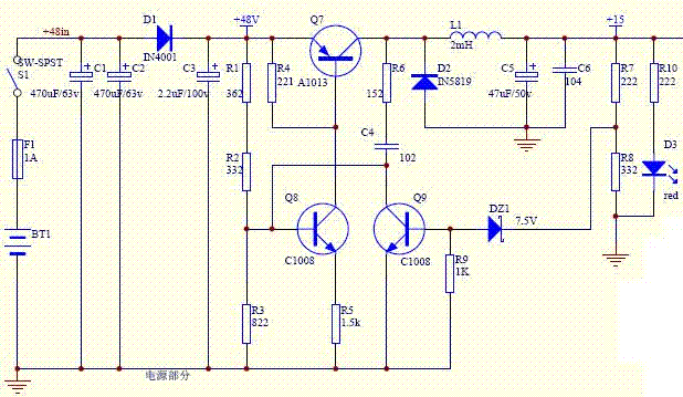
20_1173075611.gif
 

I lost my microscope.

Can you post an enlarged picture.

Better - point us to the source of the picture.
 

    wells001

    Points: 2
    Helpful Answer Positive Rating
vsmGuy said:
I lost my microscope.

Can you post an enlarged picture.

Better - point us to the source of the picture.

Sorry, it's the first time for me to post image, so I don't how to post a larger image. Can you help me?
 

Sure.

But you downloaded the picture from a site.. right ?

Better give the link.

For your question, click on the original image and you will see a larger image. Upload it here...
 

add an attachement is ok, and you file must be the pitrue format
press "Img" button and insert the url
try again!
 

    wells001

    Points: 2
    Helpful Answer Positive Rating
D2 acts as the rectifier of the system,
L1,C5 and C6 are used as a low pass filter.
 

gelo said:
D2 acts as the rectifier of the system,
L1,C5 and C6 are used as a low pass filter.
Thank you!
But, if D2 is a rectifier, is it necessary? In what condition is it on?
 

Yes it is.
The rectifier acts at the negative transition signal, it is complimentary with the signal that drives the pass element.
 

I think R4&R9 as the current startup.
 

I think that :

R5 is setting Q8's current ,and R4 set Q7's open or close,when VR4 <0.7v Q7 is off ,else VR4 >0.7v Q7 open.

feedback is that:
when the output 15V rising,VR9 is rising too,so Q9's current rise to pull down the voltage of base of Q8,so Q8's current is falling,then VR4 become low ,let Q7's current lower,so the output 15V falling
 

Thats not a linear regulator.Thats a buck converter (SMPS).
 

ynhe said:
It's a BUCK DC-DC.
I thought it was like a buck dc-dc, but it has not switching part.
 

If I were you I would determine what sets the charging current of C4 (Q7 ton) and when is it discharged (Q7 toff) and at what rate (switching).
 

This is a STEP-DOWN SWITCHING REGULATOR (BUCK REGULATOR), not a linear one.

The way to note component values is very strange, some notes is with numbering code (I do not know how to use the right word, very sorry), for example R3 = 332 = 3.3kiloOhm, others are different, for example R5 = 1.5k = 1.5 kiloOhm.

Q7, D2, L1 are main switching components.
C5, C6 = filtering and decoupling capacitors.
R4, R9 = temperature stabilizer for Q7, Q9 respective transistors. You can omit these resistors.
R5 = negative feedback resistor, that is used for stabilizing collector current of Q8.

Feedback circuit = R7-R8-DZ1-Q9 network.

Note that this kind of circuit gives fairly low efficiency (about 50% or less) and emits heat. Try to use the dedicated ICs instead.

nguyennam
 

This is a self oscillating buck converter.
R4 helps keep Q7 off when it is supposed to be off and is essential.
R1,2,3 turn Q8 on which turns Q7 on which puts power thru to the output, R5 limits the base current in Q7.

When the ouput volts get high enough DZ1 conducts turning on Q9 and charging C4, Q8,7 turn off and remain off while C4 charges the other way, during this time the ouput current of the converter circulates in the free-wheeling diode D2, C5,6 filter the ripple current to give a smoother o/p voltage.

When the base of Q8 gets back up to 0.55V or so it begins to turn on again, turning on Q7 and the process repeats, the frequency is variable depending on the load and input volts.
This is sometimes called "bang-bang" or output ripple control.
Due to the lack of positive feedback around Q8, the turn on and off of Q7 is not very fast and so the efficiency will not be as good as it could be (70-80% at a guess) - but far better than a linear pass - and the RFI/EMI will be low - Q7 will need a heatsink!

Regards, Orson Cart.
 

Status
Not open for further replies.

Similar threads

Part and Inventory Search

Welcome to EDABoard.com

Sponsor

Back
Top