Saeedk9574
Member level 3

Hi every one,
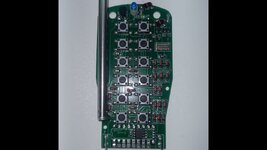
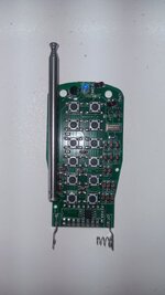
I have a few questions about the board of this RF remote control.
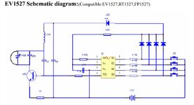
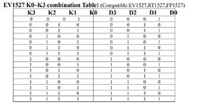
1. First of all this board uses ev1527 encoder. Although this IC has just 4 pins for buttons, this remote control has 12 buttons. How they have done such thing?
2. The second question is about the usage of these diodes (or maybe zeners). I can not understand why the have used these amount of diodes which is around 20.
3. Can I increase the range of antenna by adding extra antenna (not the TE one the two wires one)? If so, how should I calculate turns and length of them.
I have a few questions about the board of this RF remote control.
1. First of all this board uses ev1527 encoder. Although this IC has just 4 pins for buttons, this remote control has 12 buttons. How they have done such thing?
2. The second question is about the usage of these diodes (or maybe zeners). I can not understand why the have used these amount of diodes which is around 20.
3. Can I increase the range of antenna by adding extra antenna (not the TE one the two wires one)? If so, how should I calculate turns and length of them.