Continue to Site

Welcome to EDAboard.com

Welcome to our site! EDAboard.com is an international Electronics Discussion Forum focused on EDA software, circuits, schematics, books, theory, papers, asic, pld, 8051, DSP, Network, RF, Analog Design, PCB, Service Manuals... and a whole lot more! To participate you need to register. Registration is free. Click here to register now.

[SOLVED] Question regarding phase shift and oscillation criteria in VCOs

Status
Not open for further replies.

amsdesign

Member level 3
Member level 3
Joined
Aug 26, 2015
Messages
67
Helped
0
Reputation
0
Reaction score
0
Trophy points
6
Activity points
550
Hello everyone,

So far my understanding for oscillators is this :
1) Total loop phase shift should be 360 degrees
2) The loop gain should be more than 1 so that the signal is amplified in its path and not attenuated.
3) The feedback loop automatically presents a 180 phase shift of the signal


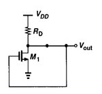
single_inverter.jpg

Assuming that inverter is a simple common source NMOS. The MOS provides a 180 phase shift and the loop feedback provides another 180 degrees. So 360 in all.
Why doesn't this serve as an inverter?
 

Would you mind to draw a transistor level circuit and explain where you see two signal inversions respectively 360° phase shift? Obviously there's only one signal inversion, switching the loop phase by 180 degree. The oscillation condition could be fullfilled if the loop gain has three poles providing additional 180 degree phase shift.

That's effectively impossible by the buillt-in RC elements of a single inverter, you need at least three inverters to form a ring-oscillator, possibly more.

Another condition is a negative loop gain at DC to allow a stable operation point for startup.
 

Would you mind to draw a transistor level circuit and explain where you see two signal inversions respectively 360° phase shift? Obviously there's only one signal inversion, switching the loop phase by 180 degree. The oscillation condition could be fullfilled if the loop gain has three poles providing additional 180 degree phase shift

Here is a schematic: single_inverter.jpg


3) The feedback loop automatically presents a 180 phase shift of the signal

The NMOS inverts the signal by 180. A feedback path is by default a 180 phase shifter. Doesn't this sum up to the 360 phase shift?
 

Here is a schematic: View attachment 121826
The NMOS inverts the signal by 180. A feedback path is by default a 180 phase shifter. Doesn't this sum up to the 360 phase shift?

...by default? Where do you see a path with additional 180deg phase shift?
 
...by default? Where do you see a path with additional 180deg phase shift?

180 degrees phase shift is produced just by virtue of negative feedback.

- - - Updated - - -

...by default? Where do you see a path with additional 180deg phase shift?

Also in a 3 inverter oscillator, each stage cotributes 180 degrees. So the total shift is 180*3? =180? I'm confused.
 

Yes - 180deg because negative feedback is established by the common source configuration.
However, where do you see ADDITIONAL 180 deg phase shift?

Regarding your question:
Three inverters give 180 deg total phase shift at DC only. This is necessary for a stable DC operating point.
However, there is only one single frequency with 360 deg total phase shift, which is realized by the signal DELAY (and/or by additional capactances at the output of the stages).
This is the oscillation frequency.
 
Yes - 180deg because negative feedback is established by the common source configuration.
However, where do you see ADDITIONAL 180 deg phase shift?

For an additional 180 phase shift if I use another inverter to create a two inverter oscialltor, the system will latch. So the solution will be to use three inverter stages.

But then again, the total phase shift will be 180*3?
 

For an additional 180 phase shift if I use another inverter to create a two inverter oscialltor, the system will latch. So the solution will be to use three inverter stages.

But then again, the total phase shift will be 180*3?

Yes, 180*3 - however, at DC only!
But for higher frequencies there is a time delay (intentional or unintentional) that is connected with additional phase shift. This allows oscillation at a frequency which results in 360 deg phase shift.
 

Yes, 180*3 - however, at DC only!
But for higher frequencies there is a time delay (intentional or unintentional) that is connected with additional phase shift. This allows oscillation at a frequency which results in 360 deg phase shift.

Hi LvW, can you kindly explain that sentence again? Are you saying at any frequency apart from 0, only two inverters are working and hence produce a 180*2 =360 phase shift?
 

Hi LvW, can you kindly explain that sentence again? Are you saying at any frequency apart from 0, only two inverters are working and hence produce a 180*2 =360 phase shift?

No - the situation is as follows:
* Each oscillator needs a feedback loop for producing a loop phase of 360 deg at the desired frequency fo. That means: POSITIVE feedback at fö.
* In addition, the oscillator needs a stable bias point, which requires NEGATIVE feedback at DC.
* For this purpose, the circuit under discussion needs odd-numbered inverter stages (at least 3).
* What happens for larger frequencies? The phase shift is larger than 3*180deg because of signal delay within the stages and additional delay (phase shift) due to capacitors at the output of the stages.
* Now - the total delay (total phase shift) must be selected/designed with the aim to produce additional 180deg at the desired oscillation frequency fo. (Another 180 deg are caused by the odd number of inverters).
* Hence, we have 360 deg phase shift at fo and the circuit oscillates. OK?
 

single_inverter.jpg


Here is an oscillator.

I understand the first 3 points.from a "phase shift" point of view, But it doesn't seem to be making sense in a circuit point of view.

1. Now, each CS stage inverts the signal by 180 degrees. So a signal entering from the input is flipped once (1st stage), and again (2nd stage) and then thrice. After two flips its back in its original form, isn't it?

2. Are you saying the Cgs of each stage adds another 90 degree shift?


Now - the total delay (total phase shift) must be selected/designed with the aim to produce additional 180deg at the desired oscillation frequency fo. (Another 180 deg are caused by the odd number of inverters).

3. What do you mean by an "additional" phase shift? Isn't each stage doing exactly that - providing a 180 shift? Are you saying that the 3 inverters provide 180 and something else needs to provide another 180?
 

A single inverter stage produces 180deg phase shift - in idealized THEORY only!
Didn`t you hear about parasitic capacitances (causing delay and additional phase shift for large frequencies) ? What about the input capacitance of the next stage?
What happens when you have an additional grounded capacitor at the output of each strage? This capacitor - together with the output resistance of each stage - forms an RC lowpass.
And a lowpass causes phase shift.
You must keep in mind that there is no IDEAL transistor inverter.

So ultimately, is the phase shift caused by the inverter or the RC of each stage? Or both?
Cause the inverter causes a 180 phase shift and a RC causes a 90 phase shift.
 

So ultimately, is the phase shift caused by the inverter or the RC of each stage? Or both?
Cause the inverter causes a 180 phase shift and a RC causes a 90 phase shift.

No - an RC lowpass causes a phase shift starting at 0 deg (DC) and assuming -90deg at infinite frequencies.
Therefore, a chain of 3 inverters can have a phase shift of (-3*180 - 3*60)=-720 deg (identical to 0 deg).
However, this applies to one single frequency only, which produces an additional phase shift of -60deg for each inverter stage.

So at one particular frequency (fo) each inverter stage is producing 60 and each RC is providing 60. So that's 6*60=360?
 

Again: NO!
If you carefully read again my answers 6, 8, 10 and 12 I am sure you will find the answer by yourself.
 

Again: NO!
If you carefully read again my answers 6, 8, 10 and 12 I am sure you will find the answer by yourself.

Here is my understanding so far. Correct me if I'm wrong

1. A CS stage produces a 180 Phase shift at DC. Any frequency above DC/ parasitic caps cause the phase shift to reduce. So at an infinite frequency, is the phase shift of a CS stage 0 degrees? (Because the input just passes to the output through Cgd)

2. A RC produces 0 phase shift at 0 frequency and 90 phase shift at infinite frequencies.

Now, is a 3 stage ring oscillator modelled as 3 inverters alone or 3 inverters along with 3 RCs?

Assuming it is modelled as both, at fo, a signal sees 6 components that want to shift its phase? Is this right?
 

Here are my answers:

Here is my understanding so far. Correct me if I'm wrong

1. A CS stage produces a 180 Phase shift at DC.

YES, but it is logical to consider it as -180deg

Any frequency above DC/ parasitic caps cause the phase shift to reduce.

No - delays and RC stages cause additiinal negative phase shifts.

So at an infinite frequency, is the phase shift of a CS stage 0 degrees? (Because the input just passes to the output through Cgd)

No - it makes no sense to consider infinite frequencies (because the do not exist). It is only a theoretical consideration to say that an RC element shift s the phase by -90 deg at infinite frequencies.

2. A RC produces 0 phase shift at 0 frequency and 90 phase shift at infinite frequencies.

Yes


Now, is a 3 stage ring oscillator modelled as 3 inverters alone or 3 inverters along with 3 RCs?

As you like: When the signal delay alone is used to cause the necessary phase shift for oscillation the frequency will be very high and not known exactly. If you use additional RC stages you can determine the frequency at lower values

Assuming it is modelled as both, at fo, a signal sees 6 components that want to shift its phase? Is this right?

Yes
 
There are right and wrong points in your new post.

It's right that the transistor is bypassed by Cgd at high frequencies, resulting in a rising phase. But the phase is not risng from zero to infinite frequency. Instead it's falling by the working of a pole, then rising again at higher frequencies. Due to additional parasitic elements, the phase is typically falling again towards infinity.

To analyse the exact behaviour of a real MOSFET over the full frequency range, you'll refer to transistor models and their equivalent circuit.

For the present problem, which is explanation of the basic ring oscillator operation, a simplified transistor model (gm plus capacitors) can be used.

Now, is a 3 stage ring oscillator modelled as 3 inverters alone or 3 inverters along with 3 RCs?
As all C's are actually inside the transistors, there's no additional RC. In your circuit, you have additional load R in parallel to the transistor output impedance, but not additional C.
 
As all C's are actually inside the transistors, there's no additional RC. In your circuit, you have additional load R in parallel to the transistor output impedance, but not additional C.

The caps are inside the transistors but they still cause a phase shift. For a one stage oscillator which sees its own Cgs as load capacitance, the maximum frequency is 180 +90 =270.

For a 3 stage oscillator, how is the calculation -for how much phase shift the inverters are producing and how much phase shift the Caps are producing- done? There are three inverters that cause a 180 phase shift and 3 Caps (as the next stage's Cgs) that cause 90 phase shift. So at fo does the sum of all the phase shift sum to 360? (On an average 60 for each block (inverter and C) or 120 for each gm and C together? )
 

Status
Not open for further replies.

Part and Inventory Search

Welcome to EDABoard.com

Sponsor

Back
Top